Software Tests as Run
DOCUMENT SCOPE
The aim of this document is to clearly explain the tests performed during the delevolpment of the subsystem.
This document is based on current but also previous versions both of hardware and software and as such be followed with care.
Tiny GS test
TinyGS module
The module used is the LILYGO ® TTGO-ESP32 LoRa32 V2 868/915MHZ which has been selected among the ones supported by the TinyGS software.

### PocketQube module
On Board Computer - Transceiver connection
The MCU used for the OBC-COMMS is STM32L476RG. This MCU family is chosen because STM32 are characterised by being ultra-low power microcontrollers and power saving is crucial for the satellite.

- Core: The STM32L476RG has an ARM Cortex-M4 core.
- Type: Microcontroller Development Board.
- Generation: STM32L4 Series of ultra-low-power MCUs.
- Flash Memory: 1 MB for general use.
- RAM: 128 KB for program and data storage.
- Peripherals: GPIO, UART, SPI, I2C, USB, ADC, DAC, Timers, DMA, RTC, and more.
Transceiver module
The PoquetQube transceiver module used is the Semtech SX1262.

This module has the following characteristics:
- Type: It is a LoRa transceiver chip.
- Generation: The SX1262 is part of Semtech’s SX12xx series of LoRa transceivers.
- Peripherals: SPI (to communicate to an external microcontroller).
- Features: Error correction, packet handling (Cyclic Redundancy Check (CRC)).
Test Set-up
TinyGS set-up
In order to test the software in the ground station, this is the setup needed to follow:
1. Heltec WiFi LoRa 32 V1 (433MHz 863-
2. 928MHz versions).
3. Heltec WiFi LoRa 32 V2 (433MHz 863-928MHz versions).
4. TTGO LoRa32 V1 (433MHz 868-915MHz versions).
5. TTGO LoRa32 V2 (433MHz 868-915MHz versions).
6. TTGO LoRa32 V2 (Manually swapped SX1267 to SX1278).
7. T-BEAM + OLED (433MHz 868-915MHz versions).
8. T-BEAM V1.0 + OLED.
9. FOSSA 1W Ground Station (433MHz 868-915MHz versions).
10. ESP32 dev board + SX126X with crystal (Custom build, OLED optional).
11. ESP32 dev board + SX126X with TCXO (Custom build, OLED optional). (k) ESP32 dev board + SX127X (Custom build, OLED optional).
12. The one used in this project is the TTGO LoRa32 V2 868-915MHz.
-
Join the TinyGS Telegram channel at the following link https://t.me/joinchat/
DmYSElZahiJGwHX6jCzB3Q.
-
Once in the Telegram general TinyGS channel, open a private chat with their bot
@TinyGS personal bot to ask for the MQTT credentials as in the following figure.
Figure 8.2: MQTT credentials.

-
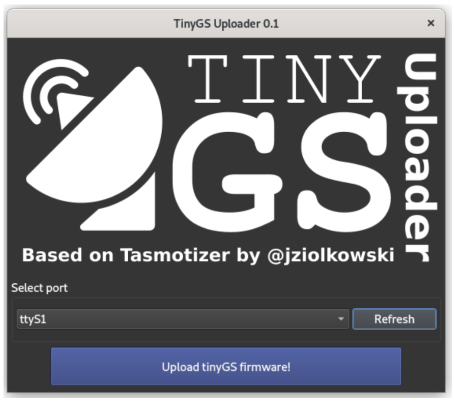
Download the TinyGS uploader from this link https://github.com/G4lile0/ TinyGS/releases, select the port, and then flash the firmware.
-
The first time the board is flashed, it creates an AP called ”My TinyGS”. Connect to that network, open a web browser, navigate to 192.168.4.1 and the TinyGS menu will appear.
-
Click on the button ”Configure parameters” and enter the following parameters specific to the ground station:
- Ground station name.
- Password for this dashboard (tinfoil2022 is the actual password).
- The WiFi SSID at which the TinyGS will be connected.
- The password for the WiFi.
- The latitude and longitude of the location where the ground station is placed.
- The timezone of the location where the ground station is placed.
- The MQTT user and password are given by the TinyGS bot.
- Select the board type used.
- OLED Bright of the display on the board, recommended a value below 100.
- Enable the TX function in order to be able to send TC to the PocketQube.
- Enable automatic tunning (when doing tests this function can be disabled, since it is only needed the communication between the PocketQube and TinyGS).
- Disable test mode, all packets need to count as actual data.
- For the board, the template should be the following one: ”name”:”[868-915] TTGO LoRA 32 v2”,”aADDR”:60,”oSDA”:21,”oSCL”:22,”oRST”:16,”pBut”:0,”led”:22,”radio”:1,”lNSS”:18,”lDIO0”:26,”lDIO1”:33,”lBUSSY”:0,”lRST”:14,”lMISO”:19,”lMOSI”:27,”lSCK”:5,”lTCXOV”:0.0.
In case of using another board, in this link https://github.com/G4lile0/ TinyGS/wiki/Board-templates there is a detailed explanation on how to create a template. - The initial radio configuration for the board should be the following: ”mode”:”LoRa”,”freq”:868,”bw”:125.0,”sf”:11
- ,”cr”:5,”sw”:18,”pwr”:5,”cl”:120,”pl”:8,”gain”:0,”crc”:true,”fldro”:1,”sat”:”Norbi”,”NORAD”:46494
- Leave advanced parameters blank.
-
Clone this repository https://github.com/juliatribo/TinyGS and flash in the board using PlatformIO.
-
Connect the PC to the same WiFi configured in the TinyGS and wait for the ground station to start. Once the TinyGS has been configured it will show an IP on the display. Open a web browser and navigate to the given IP.
-
Finally, on the website click on the station dashboard. Introduce the user: admin and the password configured before. Then, the terminal of the ground station will show up and the test can begin.


**To connect an already existing UPC NanoSat Lab TinyGS, follow these steps:**
PocketQube set-up
The STM32L476RG MCU setup is the following:

- Download the STM32CubeIDE version: 1.7.0, more recent versions might induce problems.
- Clone this repository https://github.com/juliatribo/3CAT-NXT and flash it to the STM32.
Test Results
-
Once all the set-up is ready, click on the Station Dashboard from the tinyGS and the terminal will appear.

-
In this terminal, in the enter command line, the ID (in decimal) corresponding to the telecommand which needs to be tested must be entered. In the above list, all the options are displayed. When the enter button is pressed, the corresponding message is sent to the PocketQube. A detailed explanation of the content of the packets is in the COMMS Software page.

-
On the one hand, to test the telecommands which don't have a response from the PocketQube, a breakpoint must be placed in the PocketQube code to check if the encoding and decoding have been successful:

-
On the other hand, to test telecommands with a response from the PQ, in particular, Send Telemetry and Send Config no breakpoint is needed, because the response is shown in the TinyGS terminal:
 In this picture, the blue rectangle is the PQ response. The green bytes correspond to a byte corrected thanks to Reed Solomon (it was a forced error).
 -
Then this packet is sent to the MQTT broker as well and then it can also be seen in the TinyGS web app
 Note that this packet is classified as a Norby packet and it is supposedly located below New Zealand which are false statements. This is because the Kaity structure of the NanoSatLab PocketQube has still not been sent to the TinyGS team, so the TinyGS decoder does not know how to interpret the information provided in the packet.
 -
In case of not being able to properly receive the telemetry or configuration, a NACK packet is sent to inform the satellite that a retransmission is needed. To test it, a CRC error has been forced.

-
And finally, to test the Send Data, a lot of packets are sent in a row (without encoding):


-
After all the packets are received, an ACK packet is sent to the PQ indicating which packets were properly received. It can be noted that the second packet is not properly received since there is a CRC error. In the ACK packet, after the header (which has 3 bytes), comes a vector with a length equivalent to the number of packets sent. If a packet is not received correctly, the byte with the index equal to the number of the packet failed is 0x0, otherwise, is 0x01. This is why the second byte of this vector is 0x0, because the second packet failed in this case.
-
Once the PocketQube receives the ACK, it sends back the requested packets. As can be noted, at the bottom of the last figure, the satellite has retransmitted the ordered DATA packet. It is known that this retransmitted packet is the corrupted one because its third byte (the data packet counter) is equal to 0x01, hence taking into consideration that the data packet counter starts at 0x00, this is the second packet.


Anomalies
None.
Conclusions
We are capable of establishing a communication between a Ground Station and a STM32 Nucleo + LoRa module (simulating the PocketQube).
ADCS CALIBRATION TEST
Test Description and Objectives
The goal of this test is to validate the proper functioning of the ADCS calibration function, ensuring that the magnetometer is accurately calibrated as anticipated.
Requirements Verification
| Requirement ID | Description |
|---|---|
| ADCSCAL - 01 | The ADCS calibration telecommand is correctly received and processed. |
| ADCSCAL - 02 | The instruments of the ADCS subsystems are correctly calibrated. |
Test Set-Up
Materials
- OBC-COMMS board
- ADCS board
- TinyGS (ground station)
- Attenuators
- Rotating machine
- Computer
Setup
The test setup for this experiment is straightforward:
Establish a connection between the OBC-COMMS and ADCS boards, enabling seamless information transfer from COMMS to the ADCS subsystem.
Prepare a ground station, with the option to use attenuators to replicate space conditions, we will be sending the telecommand from here.
Following successful calibration, employ a rotating machine to simulate the satellite's rotation in all directions. All data will be read using a computer.
Pass/Fail Criteria
The sole instrument undergoing calibration is the magnetometer. To assess its accuracy, we can perform rotations in all directions and examine whether the obtained results form a perfect sphere. Successful calibration is indicated if the data conforms to a spherical shape; conversely, a lack of conformity signifies an unsuccessful calibration.

Test Plan
Step 1: Communication
Step one involves establishing communication between the ground station and our PocketQube. To achieve this, we will follow the steps outlined in several previous tests, as explained in the preceding test or the RX-TX test.
Step 2: Telecommand
Upon establishing communication, the next step is to send the ADCS calibration telecommand. To verify the correct reception and execution of the ADCS calibration, breakpoints can be strategically placed within the process telecommand function for monitoring.
Step 3: Rotation
Upon receiving the telecommand and uploading the calibration, the success of the calibration can be demonstrated by measuring the magnetometer in all three axes. The results can then be plotted using a computer, and a successful calibration is indicated by the formation of a perfect sphere in the plotted data. For rotating at a constant rate we can use a rotating wheel.
MULTIPLE PACKET TEST
Test Description and Objectives
The objective of this test is to prove that the recent modifications of the code have solved the issue we had regarding the reception and registering of longer than 3 packet telecommands.
Requirements Verification
| Requirement ID | Description |
|---|---|
| MULPT - 01 | Be able to transmit all packets using a TinyGS. |
| MULPT - 02 | Be able to receive and register all the packets. |
Test Set-Up
Materials
- Computer
- TinyGS
- OBC-COMMS board connected to antenna or STM32 Nucleo + LoRa module.
Setup
Prepare the ground station and Nucleo + LoRa, as explained in previous tests (TinyGS test for example). If we choose to use the OBC-COMMS board instead, the setup should be the following:

Pass/Fail Criteria
If the stipulated conditions are fulfilled, specifically, successful transmission, reception, and registration of telecommands with multiple packets, we will deem this test as successful. The telecommands that satisfy these criteria include the transmission of TLE telecommands and the execution of ADCS calibration telecommands.
Test Plan
Step 1: TinyGS
Once the Ground Station and the receiving component of our system (either STM32 Nucleo + LoRa or the OBC-COMMS board) have been set up, the remaining task is to transmit either the TLE telecommands or initiate the execution of ADCS calibration telecommands.

Step 2: STM32 + LoRa or OBC-COMMS board
Once the telecommand is sent the COMMS subsystem should be receiving the telecommand (if not, check RX-TX test in COMMS SSV testing).
Once the telecommands are received we can check that they have been registered as planned using the Utility program (the one we use to check registers).
Test Results
Step 1:
Both telecommands can be sent by the ground station.
Step 2:
- Can now successfully receive up to 3 packets (previously it was 1 packet)
- Still can’t receive up to 5 packets because the 2 missing packets don’t appear to be received by the system, still working on the issue.
- Possible issue with the OBC task.
Anomalies
Still cannot solve the issue where only a part of the packets are reveived. No appearing problem with the reception buffer.
Conclusions
Possible solution is to separate the TLE telecommand in 2 separate telecommands, a first part with 3 packets and a second part with 2 packets. Test will need to be redone.
NON-HARDCODED TELECOMMAND TEST
Test Description and Objectives
Currently, the telecommand contents are hardcoded, which is not ideal. The goal is to enable the modification of telecommand contents without the need for code recompilation. Changes were made to the code to address this issue, and this test plan aims to demonstrate the effectiveness of these modifications.
Requirements Verification
| Requirement ID | Description |
|---|---|
| NHTT - 01 | Transmission of the telecommands is done correctly. |
| NHTT - 02 | Reception and processing of the telecommands is done correctly. |
| NHTT - 03 | Registers are uploaded. |
Test Set-Up
Materials
- Computer
- TinyGS
- OBC-COMMS board connected to antenna or STM32 Nucleo + LoRa module.
Setup
Set up both the ground station and reception modules according to the instructions provided in the previous tests.
Pass/Fail Criteria
The success criteria for this test involve the accurate transmission, reception, and correct processing of telecommands. The test will be deemed successful if these tasks are executed correctly.
Test Plan
Step 1: Transmission
After preparing the ground station and the COMMS subsystem we can begin transmiting the telecommands.
Step 2: Register analysis
After receiving and processing the telecommands, the next step is to verify the accurate storage of information by the On-Board Computer. It is essential to ensure that the information is stored efficiently and that the addresses of the stored values are no longer hardcoded. To perform this verification, tools such as "Utility" can be employed to inspect the registers and confirm the correct storage of information.
VGA-COMMS TEST
Test Description and Objectives
The objective of this test is to take a picture with the VGA Camera (P/L1), ask for it through a telecommand (SEND_DATA), and receive it successfully. The test will be done without the use of TinyGS as it was suspected it was a source of errors (MQTT).
Requirements Verification
| Requirement ID | Description |
|---|---|
| VCT - 01 | Take a picture with the VGA Camera connected to OBC-COMMS. |
| VCT - 02 | Receive a TTL (SEND_DATA) and execute it. |
| VCT - 03 | Be able to receive the data sent. |
Test Set-Up
Materials
- OBC-COMMS Board + Lateral Board
- HelTec CubeCell Dev-Board (HTCC-AB01)
- PTC06 VGA Camera
Setup
Prepare the OBC-COMMS PCB + Lateral Board, as explained in previous tests, and the CubeCell, acting as our ground station. The VGA should be connected to the OBC-COMMS PCB directly.
Pass/Fail Criteria
The test is considered to be passed as long as a picture is taken, sent after the reception of a TTL, and received by the ground station with no packet loss.
Test Plan
Step 1: Taking a picture (as of start-up)
The code will begin by taking a photo with an approximate length of around 9kB, which is the amount of data expected to be able to transmit during a pass. (0x11,0xFF).
Step 2: Sending and executing the SEND_DATA telecommand
The TTL will be send through the CubeCell and executed by the OBC-COMMS PCB.
Step 3: Receiving the photo
The packets will be received in the GS and then decoded (removal of headers and non picture information) in order to recover our photo.
Test Results
Step 1:
The photo was succesfully taken.
Step 2:
The TTL was sent, received and executed (TX of data).
Step 3:
Data was successfully received and decoded, yielding the exact same picture as taken.


Original picture of some members of the PoCat team. Received picture through the procedure.
Anomalies
There seems to appear some issues to enter the COMMS Task if the Flash task is active, commenting the flash task doesn't affect the process and allows for the execution of the test seamlessly. This issue is to be revised thoroughly.
Conclusions
The COMMS-OBC is proved be able to execute a payload task and to provide lossless data transmission under the aforementioned conditions. Further testing with attenuation is required so as to simulate real conditions. The test is successfully passed.
COMMS-COMMS TEST
Test Description and Objectives
The objective of this test is to prove that data share between PQ2 and PQ3 is possible. The test will be conducted with an OBC-COMMS PCB and a Nucleo Board, as no extra PCB's are available at the moment. It is a preliminary test, and further work should be done.
Requirements Verification
| Requirement ID | Description |
|---|---|
| CCT - 01 | Be able to transmit a telecommand through the OBC-COMMS. |
| CCT - 02 | Be able to receive said telecommand in the Nucleo and execute it properly. |
| CCT - 03 | Be able to receive the data sent by the Nucleo Board in the OBC-COMMS. |
Test Set-Up
Materials
- Nucleo L476RG + LoRa
- OBC-COMMS Board + Lateral Board
Setup
Prepare the OBC-COMMS PCB + Lateral Board and Nucleo + LoRa, as explained in previous tests (TinyGS test for example). They should be separated by at least 30cm, in this case both systems were connected to different computers. A small code stub in the OBC-COMMS was developed so as to send the TTL.
Pass/Fail Criteria
If the stipulated conditions are fulfilled, specifically, successful transmission and reception on both sides, without any packet loss, the test will be considered passed
Test Plan
Step 1: Sending a Telecommand
Send the SEND_DATA telecommand packet through OBC-COMMS.
Step 2: Receiving and executing the telecommand
We expect to receive the TTL and execute it properly, sending the designated data.
Step 3: Receiving the data
We expect to receive the data sent by the Nucleo and store it in a buffer in the OBC-COMMS Board.
Test Results
Step 1:
Telecommand was successfully sent.
Step 2:
Telecommand was successfully sent and executed.
Step 3:
The sent data was partially received, missing some of the initial packets.
Conclusions
Communication between two OBC-COMMS Boards should be feasible as proved by this test. Despite that, the test wasn't passed as in ideal conditions not all packets were received. Further investigation, with a more realistic setup and different code proposals are required.
FREQUENCY SWITCHING TEST
Test Description and Objectives
The objective of this test is to prove that frequency switching is possible, without a complete reset of the transceiver.
Requirements Verification
| Requirement ID | Description |
|---|---|
| FST - 01 | Be able to transmit in our main frequency (868MHz). |
| FST - 02 | Be able to switch transmission frequency and transmit on it (870MHz in these case). |
| FST - 03 | Be able to receive the data sent in both frequencies. |
Test Set-Up
Materials
- OBC-COMMS Board + Lateral Board
- HelTec CubeCell Dev-Board (HTCC-AB01)
- Tiny SA
Setup
Prepare the OBC-COMMS PCB + Lateral Board, as explained in previous tests, and the CubeCell, acting as our ground station. They should be separated by at least 30cm. The lines implemented at the beginning of the COMMS loop were:

Note the delays in order to ensure packets are fully sent. In a real case the switching will be done when not transmitting so it shouldn't be a necessary constraint.
Pass/Fail Criteria
If TX frequencies are switched and packets can be received in both of them the test will be considered passed.
Test Plan
Step 1: Sending and receiving data in one frequency
Step 2: Switch frequency
Step 3: Sending and receiving data in the other frequency
Test Results
Step 1:
Data was successfully sent and received in 868MHz
Step 2:
No measurable changes.
Step 3:
Data was successfully sent and received in 870MHz
Anomalies
The same test was done with less delay, and no frequency switching was observed, probably due to the fact that packets weren't fully sent.
Conclusions
Frequency switching was successfully executed and the test is considered passed.
No Comments