Hardware Design
Introduction
The hardware of the Attitude Determination and Control System (ADCS) is essential for the satellite’s operation. Without it, the satellite would be unable to gather critical data about its orientation and environment in space, which is necessary for executing various functions. The ADCS hardware enables the satellite to determine its position, control its orientation, and stabilize itself, ensuring that it can carry out mission objectives such as data collection and communication.
Design Choices
The design of the ADCS follows a simple philosophy, all components and sensors are selected for their low power use, good performance, and reasonable cost. The goal was to choose parts that are reliable and fit within the PocketQube’s limited power and budget.
Actuator selection
There were several options for implementing an actuator in the PocketQube. As explained in the ADCS introduction section, there are two ways to achieve attitude control: passive control, using a magnet as an actuator, and active control, using reaction wheels or magnetorquers.
The passive option was considered, as it is the primary method used for achieving attitude control. However, one drawback of this approach is the limited control over pointing precision.
For the active option, using reaction wheels was discarded because the size and power consumption requirements of a PocketQube are incompatible with this approach. Thus, the remaining option for active attitude control was the magnetorquers. This technique is relatively new, and this would be one of the first PocketQubes to implement it. Additionally, it offers the pointing accuracy needed to conduct the required measurements. For these reasons, magnetorquers were chosen.
Sensors election
Regarding the sensors, the main objective was to find ones compatible with the I2C protocol.
Why the I2C protocol is the selected in the Satellite?
The I2C protocol is mainly used for enabling communication between multiple integrated circuits on the same board with minimal wiring. It is based on a two-wire serial communication protocol, which uses one line for data, called SDA, and another for the clock signal, called SCL, allowing for simple, low-speed data exchange over short distances.
I2C is used in applications where several peripheral devices (like sensors, memory devices, or display drivers) need to communicate with a central microcontroller or processor. It also has low power consumption, which is crucial in satellite applications.
2.2.1 Magnetometer
The magnetometer IC that will be used for the ADCS is the MMC5983MA, developed by MEMSIC, is a high-precision, 3-axis magnetometer known for its small size and low power consumption, making it particularly suitable for small satellite applications like PocketQubes. Datasheet: MMC5983MA
|
Attribute |
Specification |
|---|---|
|
Name |
MMC5983MA |
|
Supplier/Manufacturer |
Mouser, Memsic |
|
Power Consumption |
212.19 μW |
|
Field Range |
± 8 G |
|
Resolution |
0.25 mG per LSB |
|
Operation Bits |
16 bits |
|
Sensitivity |
± 4096 Counts/G |
|
RMS Noise |
0.4 mG |
2.2.2 Gyroscope
The Gyroscope IC that will be used for the ADCS is the IIM-42652, manufactured by TDK InvenSense, is a compact, high-performance 6-axis Inertial Measurement Unit (IMU) combining a 3-axis accelerometer and 3-axis gyroscope. Its design and capabilities make it well-suited for small satellites like PocketQubes, which require efficient, low-power, and reliable orientation and motion data for various tasks such as attitude determination, stabilization, and control. Datasheet: IIM-42652
|
Attribute |
Specification |
|---|---|
|
Name |
IIM-42652 |
|
Supplier/Manufacturer |
Mouser, TDK InvenSense |
|
Power Consumption |
1.91 mW |
|
Scale Range |
±15.625 °/s, ±31.25 °/s, ±62.5 °/s, ±125 °/s, ±250 °/s |
|
Operation Bits |
16 bits |
|
Sensitivity Scale Factor |
2097.2 LSB/(°/s), 1048.6 LSB/(°/s), 524.3 LSB/(°/s), 262 LSB/(°/s), ç 131 LSB/(°/s) |
|
RMS Noise |
0.038 °/s-rms |
2.2.3 Temperature Sensors
The temperature sensors that will be used are named TCN75A, createdby Microchip Technology, designed for low-power applications and precise temperature measurement. Its compact size, low power usage, and simplicity make it suitable for use in small satellite platforms like PocketQubes, especially where basic thermal monitoring is needed. Datasheet: TCN75AVOA
|
Attribute |
Specification |
|---|---|
|
Name |
TCN75A |
|
Supplier/Manufacturer |
Mouser, Microchip Technology |
|
Power Consumption |
1.65 mW |
|
Field Range |
-40 °C to 125 °C |
|
Accuracy |
±1 °C |
|
Resolution |
0.0625 °C to 0.5 °C |
|
Operation Bits |
16 bits |

2.2.4 Photodiodes
The SLCD-61N8 is a reliable and cost-effective silicon photodiode designed for light sensing and power generation. It provides visible to infrared sensitivity, high efficiency, low capacitance, and excellent durability. The choice of photodiode is flexible, and alternative models with similar wavelength sensitivity to sunlight can also be considered for use. Datasheet: SLCD-61N8
|
Attribute |
Specification |
|---|---|
|
Name |
SLCD-61N8 |
|
Supplier/Manufacturer |
Mouser, Advanced Photonix |
|
Short Circuit Current |
170 μA |
|
Open Circuit Voltage |
0.4 V |
|
Maximum Sensitivity Wavelength |
930 nm |
|
Acceptance Half Angle |
60 deg |

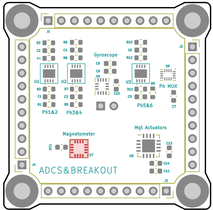
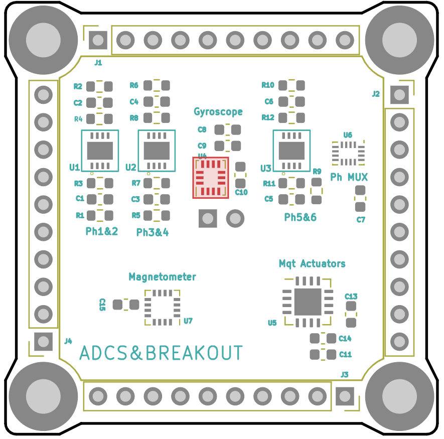
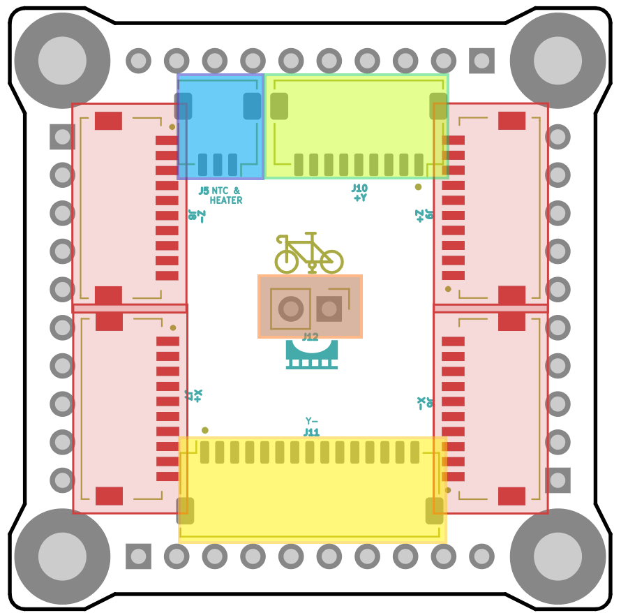
PCB Design
This is the PCB design of the ADCS. The board is also used as an interface between the other subsystems and the outer boards and the battery. It is divided into 5 different blocs.
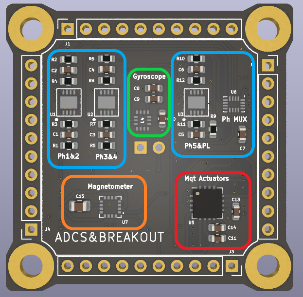
- Photodiode block: This block is responsible for receiving information about the sunlight received on the surface of the PocketQube. A photodiode is located on each lateral board, as well as on the top and bottom boards. Each photodiode receives sunlight and generates a current in response. This current is amplified using an operational amplifier, which also converts the intensity into voltage so it can be read by the Analog-to-Digital Converter (ADC) of the On-Board Computer (OBC). The OBC in order to select a photodiode to read, it controls a multiplexer used for selecting the output of a specific operational amplifier.
- Gyroscope block: This section of the PCB is in charge of obtaining the information about what angular velocity is rotating the satellite in all three axis. It is formed by the IIM-42652 chip and some resistors.
- Magnetometer: This part of the PCB serves to measure the value of the magnetic field at the PocketQube coordinates. The chip used is the MMC5983MA and is accompanied by a capacitor.
- Magnetorquer driver: This chip is the responsible for providing the selected current to the magnetorquers. In order to make the chip work, a LED has been added for each magnetorquer in its outer board. The IC used is the BD2606MVV followed by three capacitors.
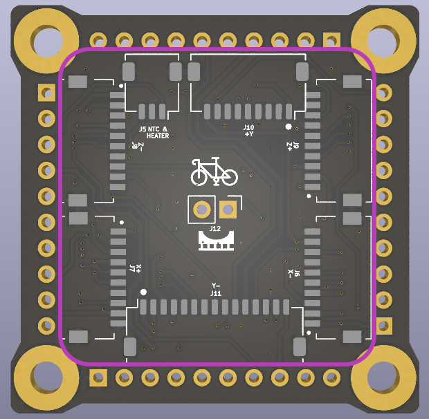
- Bottom connectors: In the backside of the PCB there are located 7 connectors. These connectors are used as an interface for each outer board of the Satellite. These pins contains the Photodiodes inputs and the magnetorquer connexions. In addition it also is used for connecting the temperature sensors located in the outer boards to the OBC and for connecting the battery heater and the battery temperature sensor.
Full schematic
Passive components
Integrated circuits
|
Component |
Type |
Quantity |
Manufacturer number |
Connectors
|
Component |
Type |
Quantity |
Manufacturer number |
A more detailed information about each vertical PIN and bottom pin is shown in the following picture:
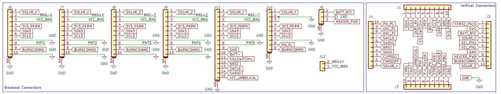
- Connectors J6,J7,J8 & J9: These connectors are used for the lateral boards and serve multiple functions. The pins include the following: the input for the voltage generated by the solar cells (SOLAR_X), the input and output for the magnetorquers (VCC_MAG and MAG ‘±X ±Z’), the I²C communication buses (SDA and SCL), the input for the photodiode, and an output for injecting the required voltage into the resistor used for antenna deployment. This output (BURNCOMMS) is utilized if the antenna is placed on the corresponding lateral board.
- Connector J10: This connector is used for the top payload. If the a new payload is being developed, the obligatory pins needed are the Photodiode PIN and its corresponding ground pin. The rest of the PINS can be modified according to the requirements of the new payload. In case of using the OpenPOcketQube Kit paylaods, this connector is used only in the VGA camera.
- Connector J11: This connector is used for the bottom board it has included the same pins as the J6, J7, J8 & J9 connectors, but including some new ones. The functionalities of the new pins are the following: BATT- & KILLSWITCH+, used for activating the EPS after the deployment of the satellite. Also the pins used for debuging the satellite using the umbilical connector located at the bottom PCB are located in J11 (NRST, SWCLK,SWDIO & VCC umbilical). Finally, there is the SWO pin, which can be used for any functionality, it is a programable pin.
- Connector J5: Connector used for the battery heater and temperature sensors located in the battery compartment.
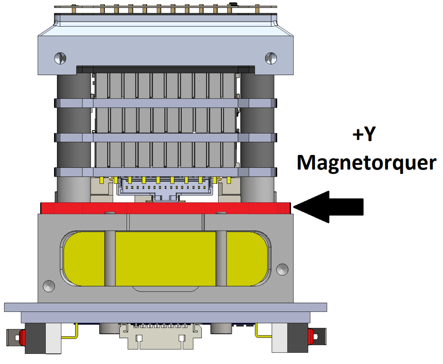
- Connector J12: Used for connecting the magnetorquer +Y PCB located under the ADCS.
Magnetorquer actuators
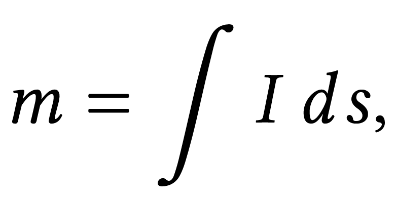
The magnetorquers are responsible for achieving attitude control in the PQ. These devices function as magnetic dipoles and when an electric current is passed through them, they create a magnetic moment. This magnetic moment interacts with the Earth’s magnetic field, generating a torque that adjusts the satellite’s orientation. This interaction can be represented as:
![]()
The calculation of the magnetic moment depends on the type of magnetorquer used. In the PocketQube, planar helical coils serve as magnetorquers, embedded in the outer boards along each axis, except for the +Y axis, where they are positioned within the inner layers of the satellite. These coils are distributed across the boards in four layers.

Magnetorquer characteristics
|
|
+Y PCB |
Lateral & Bottom |
|
Separation between turns |
0.2 mm |
0.2 mm |
|
Height |
35 µm |
35 µm |
|
Width of the trail |
0.18 cm |
0.18 cm |
|
Material of the trail |
Copper |
Copper |
|
Dimensions |
28 x 28 mm |
32 x 32 mm |
|
Resistance |
89.91 Ω |
88.3 Ω |
|
Turns per layer |
42 |
38 |
|
Maximum moment |
3.63·E03 a·m^2 |
3.2·E03 a·m^22 |
Magnetorquer injected current formula derivation
In order to compute the intensity, firstly the total magnetic moment expression shall be derivated. The magnetic moment of a coil is,
As we have a combination of coils the total magnetic moment will be,
To compute the total magnetic moment, the magnetorquer coils will be modeled as square coils, with each turn represented as an individual square coil,
These coils are separated by distances 𝐝outer = 0.2 mm and 𝐝top = 0.18 mm. The label, "outer" refers to the magnetorquers located on the outer boards, and the label "inner" refers to the magnetorquer located inside the satellite.
The total magnetic moment of the magnetorquers will be computed as:
Where 𝐍layers is the number of layers of the magnetorquer, 𝐈o is the required injected intensity, and 𝐒𝐢 the surface ofthe coil with the turn number 𝐢. The expression that calculates the surface of each turn is:
![]()
where 𝐋 is the size of the bigger coil and 𝐖𝐢 the amplitude of the conductor of the coil. In addition 𝐝𝐢 and 𝐖𝐢 can be 𝐝𝐢(𝐢𝐧𝐧𝐞𝐫), 𝐝𝐢(𝐭𝐨𝐩), 𝐖𝐢(𝐢𝐧𝐧𝐞𝐫), 𝐖𝐢(𝐭𝐨𝐩). Isolating the required current from the equation we obtain that:
Magnetorquer polarisation
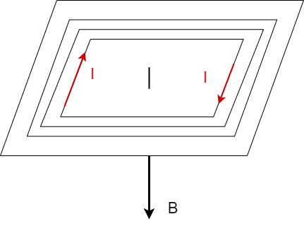
Finally one of the most important things to characterize of the magnetorquers is their polarisation. The polarisation of a coil refers to the direction of the magnetic fiel generated when some intensity is injected throught the coils. The polarisation should follow the right hand rule.
In our case as shown in,
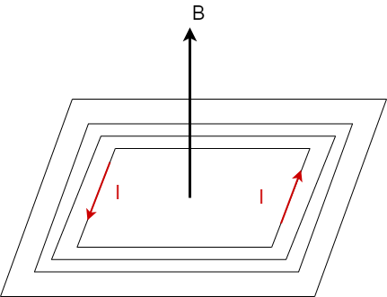
If the current flows clockwise, the magnetic field direction is perpendicular towards the bottom face of the plane formed by the coils of the magnetorquer. Similarly, if the current flows counterclockwise, the magnetic field direction is perpendicular towards the top face of the plane,
No Comments