Software Design
COMMS Software is integrated within the MCU and designed as a state machine that transitions mainly due to the recival and transmission events. Most of the relevant code is encapsulated within the COMMS Task, in terms of FreeRTOS structure. The software is then responsible for the proper handling of each telecommand received as well as beacon transmission among other functinalities such as:
- Cessation of transmissions for a specified time.
- Satellite state manual transitions.
- Subsystem reconfiguration.
- On-Board Computer and memory resets.
- Verification of operations through ACK/NACK.
- Rejection of non-mission packets through packet ID’s.
In terms of telemetry, in a nominal state:
- On-Request telemetry (beacon) transmission (both historic and instant).
- Modifiable, periodic transmission of telemetry (beacon).
- UNIX Timestamped packets.
- Payload data division into packets for downlink.
- Verification of downlink operations via ACK/NACK.
Do note that as the PQ enters either SUNSAFE or SURVIVAL TT&C becomes heavily restricted in favour of mission preservation. In SUNSAFE the only telemetry available will be the periodically transmitted beacon, dedicating all other task time to active listening.
In SURVIVAL the telemetry capabilities of the satellite are completely deactivated until a change of state occurs, only actively listening for telecommand for a set period of time. In case of TC reception, the most critical beacon data is sent in response in order to assess the spacecraft state.
State Machine
As of current design the COMMS State Machine is composed by a total of five states. The first state corresponds to STARTUP, where the transciever is reset and initialized. After initialization the radio will start alternating between its sleep mode and CAD or reception mode (tbd), all within the SLEEP state.
In case of being in CAD Mode and having detected activity the machine will enter the RX state and actively listen for a specified value of time. In case of surpassing said value with no packets received the machine will go back to SLEEP, and so will do in case of receiving a packet not sent by the GS. An RX Error during this process also returns the machine to SLEEP.
In case of not being in CAD Mode in the SLEEP state a successful packet receival will send the machine to the RX state, so as to process the TLC. This will also happen when as TLC is received in the RX state when CAD Mode in set on.
The successful receival of a TLC will enter us into the TX state. Here either p/l data will be sent, awaiting for ACK's in this case (ARQ), returning to RX (after TxDone), or telemetry (!ARQ), sending the machine to the SLEEP state (after TxDone).
As the time to send a beacon arrives the machine is to be notified by the OBC and enter the TX state to transmit it.
During the RX state it might occur that a TLC is received indicating transciever parameters are to be changed. This will send the machine to the STDBY (Standby) state, as it is required to do so. In case of having to reset the SX1262 this state will also be present as an intermediary before STARTUP.
The STARTUP state can also be forced to enter through a OBC Notification to the task itself. The state machine also checks for IRQ and OBC notifications in every iteration, independently of the current state.

Figure 1: COMMS State Machine
EDAC & ACK's
As of current design both uplink and downlink telecomunications are subject to a similar EDAC procedure. As is discussed before different coding rates might be chosen in order to trade-off security for speed and vice-versa, leaving an open space for different options.
LoRa already puts in use it's own convolutional coding in every transmission, so no further layer is added. On the other hand interleaving is used in order to minimize the burst errors expected to occur due to atmospheric scintillation and other variables. This means that messages are to be manually encoded and decoded at both nodes of communication.
When it comes to verifying transactions ACK's are an essential part of the game. All telecommands that do not induce the direct transmission of data to the GS have been atached the sending of an ACK as a part of their processing. Thankfully in many cases the direct purpose of a TLC is to retrieve data from the PQ, meaning that receiving said data is enough of an ACK.
Extracting payload data gets more tricky. As of current design a Stop-And-Wait (Sliding Window of step w)? ARQ is implemented in order to ensure zero loss of data in case of link loss during transmission. This is done through the request of a specified number of packets (window). In case of successfully receiving all the expected packets the GS might send a TLC (with an incorpored ACK) requesting the next batch or data or indicating a new operation.
The aforementioned case can be found when the PQ has to send multiple packets in a single operation to the GS. The opposite might occur, as it does when sending the TLE to the PQ. The TLE TLC consists of multiple packets. The approach taken is to send the full TLE TLC and await for the receival of an ACK. Should a NACK arrive all packets are to be sent again, as the PQ will expect the GS to do so.
Further visual and specific information is found on the next sections about this topic.
Encoding
All data, both in uplink and downlink, is interleaved in order to minimize the effects of burst errors. Further encoding is done outside our scope by the LoRa modules, with a set coding rate (CR) of 4/5. CRC is also provided by the LoRa modules. A simple diagram is provided next:

Figure 2: Encoding and Decoding Schemes
Note that the data is not only further encoded and decoded but also modulated and demodulated by the transcieverswithout any other device or software processing.
Interleaving
Interleaving is an encoding technique which is based on the reordering of bytes aiming to prevent burst errors. It is of great relevance when the information contained in a byte also provides information about it's neighbour, such as in the case of payload data. An example of how interleaving works will is shown below.
First of all, the data before the interleaving process is divided into 4 codewords, and each one is presented in a different colour.
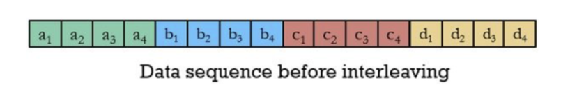
Figure 3: Interleaving example step 1: Data without interleaving.
The second step is to organize the codewords in columns forming a 4x4 matrix.
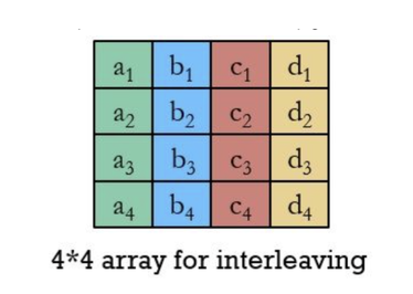
Figure 4: Interleaving example step 2: Data in a square array.
And finally, the data is retrieved row by row from the 4x4 matrix.

Figure 5: Interleaving example step 3: Data after interleaving.
This way, if there is a burst error such as the one shown in the previous picture (the white bytes), instead of affecting a whole codeword, it is spread through the data sequence (as seen in the figure below), thus errors are isolated and easier to correct.
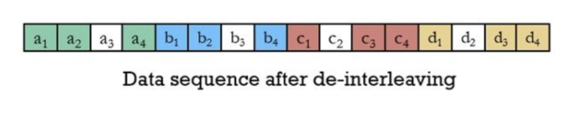
Figure 6: Interleaving example step 4: Data after de-interleaving.
This will only work if the packet lenght is a square number, therefore padding is be added in cases where this condition is not met.
Telecommands
This section is oudated in respect to current design. New telecommands have been designed in order to facilitate debugging, testing and providing a more thorough control of the spacecraft. These can be found on the Operations book. Reed Salomon encoding has also been dropped out. All the aforementioned changes will be reflected on future versions of the Wiki and software.
Telecommands are the mesages or instructions send by the Ground Station to the satelite that indicate it to perform a specified task. The opposite data, the one sent by the spacecraft to the GS, receives the name of telemetry.
RESET
This telecommand orders the PocketQube to do a soft reset. This is required in case of software malfunctioning when the satellite is experiencing unexpected behaviour.
The structure of this telecommand is:
- 3 bytes of header formed by 2 bytes of PIN and 1 byte of telecommand ID. The PIN ID is a preventive measure to avoid someone non-authorised from sending order executions to the PocketQube and jeopardizing the mission, - 4 bytes of a Unix time timestamp, - 1 end byte equivalent to 0xFF.
Then, this content is interleaved and the output is transmitted.

EXIT_STATE
This telecommand, as its own name implies, requests the exit from a state. The state desired to exit is sent as a parameter inside the telecommand.
The structure of this telecommand is:
- 3 bytes of header composed of 2 bytes of PIN and 1 byte of telecommand ID, - 2 bytes informing which is the state the PocketQube must exit. Three possible states are given, each one presented with 4 bits set to 1 in order to provide redundancy. The contingency state is represented by the 4 first bits from the first byte (these 2 bytes should look like this 0xF0 0x0), the survival state is represented by the following 4 bits (0x0F 0x0), and finally, the survival state is represented by the first 4 bits of the second byte (0x0 0xF0). The last 4 bits of the second byte are for padding, - 4 bytes of a Unix time timestamp, - 1 end byte equivalent to 0xFF and -, and - 6 bytes of padding in order to reach the next multiple of 2^number (in this case 16).
Then, this content is interleaved and the output is transmitted.

TLE
In fact, a Two Line Element has 3 lines. The first one is for the satellite name, thus, in this case, it can be neglected. Then, two lines of 69 Bytes each contain the orbital elements from which the orbit of the satellite can be computed. This telecommand is used to update the orbit information in the PocketQube needed to propagate the orbit.
As commented previously, the maximum payload size allowed is 48 bytes (taking into account the multiples of 16). Thus, 4 packets will be needed to send the two lines of 69 bytes from the TLE because, from the 48 bytes, only 34 are reserved for data.
Two designs have been implemented given the fact that the last packet only transports 18 bytes of the TLE. The first 3 packets will follow this structure:
-
3 bytes of header formed by 2 bytes of PIN and 1 byte of telecommand ID,
-
40 bytes of the TLE orbital elements,
-
4 bytes of a Unix time timestamp,
-
1 end byte equivalent to 0xFF. Regarding the last packet, it will have the following structure:
-
3 bytes of header formed by 2 bytes of PIN and 1 byte of telecommand ID,
-
18 bytes of the TLE orbital elements,
-
4 bytes of a Unix time timestamp,
-
1 end byte equivalent to 0xFF.
-
22 bytes of '0''s. Each packet will also be interleaved before being sent.

SEND_DATA
This telecommand orders the PocketQube to send the payload data.
The structure of this telecommand is:
- 3 bytes of header formed by 2 bytes of PIN and 1 byte of telecommand ID,
- 1 byte to inform which picture size is desired (there are two choices: big or small),
- 4 bytes of a Unix time timestamp,
- 1 end byte equivalent to 0xFF, and
- 7 byte of padding in order to reach the next multiple of 16 (in this case 16). Then, this content is interleaved and the output is transmitted.

SEND_TELEMETRY
This telecommand orders the PocketQube to send the telemetry data so it does not have to wait for the beacon to be transmitted.
The structure of this telecommand is:
- 3 bytes of header formed by 2 bytes of PIN and 1 byte of telecommand ID,
- 4 bytes of a Unix time timestamp,
- 1 end byte equivalent to 0xFF. Then, this content is interleaved and the output is transmitted.

ACK_DATA
In the payload data transmission, since lots of packets are sent in a row, to avoid the interruption of the transmission, only a packet will be sent at the end with the information of the packets that were received and the ones that were not.
The structure of this packet depends on the number of received packets:
- 3 bytes of header formed by 2 bytes of PIN and 1 byte of telecommand ID, - As many bytes as needed in order to acknowledge each data packet received (one byte per packet). It can go up to 34 bytes, and in case of not enough, 2 ACK DATA packets will be needed, - 4 bytes of a Unix time timestamp, - 1 end byte equivalent to 0xFF and 10 bytes for padding.
Then, this content is interleaved and the output is transmitted. In this packet structure, padding might be added if the number of ACK bytes is not enough to construct a packet with a length multiple of 2^#.

ADCS_CALIBRATION
This packet sends the whole ADCS parameters needed to calibrate and then, when the PocketQube receives it, the calibration is carried out.
This structure will be changed in the near future.


UPLINK_CONFIG
The UPLINK CONFIG telecommand sends the desired PocketQube configuration to the satellite and once it is received, the parameters are compared to the ones stored in the PocketQube. If the parameters do not match, the values are updated.
The structure of the telecommand is:
-
3 bytes of header formed by 2 bytes of PIN and 1 byte of telecommand ID,
-
18 bytes of configuration data,
-
4 bytes of a Unix time timestamp,
-
1 end byte equivalent to 0xFF, and
-
11 bytes of padding to reach the next multiple of 2^#, which is 32 bytes. The configuration data can be broken into:
-
4 bytes of Unix time used for synchronization, - 4 bytes of communication parameters such as spreading factor, coding rate, frequency etc., - 1 byte for the KP constant (the equilibrium constant), and - 3 bytes for the battery thresholds of the nominal, the low and the critical states (one byte each).
Then, this content is interleaved and the output is transmitted.

CHANGE_TIMEOUT
This telecommand requests a change of receiving timeout of the PocketQube. This might be useful if the spreading factor is increased which implies slower transmissions.
The structure of this telecommand is:
- 3 bytes of header formed by 2 bytes of PIN and 1 byte of telecommand ID,
- 2 bytes to send the new desired timeout in milliseconds,
- 4 bytes of a Unix time timestamp,
- 1 end byte equivalent to 0xFF.
- 6 bytes of padding to reach the next multiple of 2^#, which is 16 bytes. Then, this content is interleaved and the output is transmitted.

ACTIVATE_PAYLOAD
This telecommand is sent when the payload must be activated either for a photo or for an RFI measurement (depending on the payload of the POCAT). All the characteristics of the photo or measurement along with the payload configuration are specified in the telecommand.
The structure of this telecommand is:
- 3 bytes of header formed by 2 bytes of PIN and 1 byte of telecommand ID,
- 30 bytes for the payload activation specifications,
- 4 bytes of a Unix time timestamp,
- 1 end byte equivalent to 0xFF, and
- 10 bytes of padding to reach the next multiple of 2^#, which is 48 bytes. The payload activation specifications are divided into 3 blocks:
First of all, 6 bytes with information related to the photo (in case the PQ has no camera as payload these bytes are set to 0), which can be broken down into:
-
4 bytes of Unix time to inform when to take the next payload data acquisition,
-
1 byte to request a specific compression for the photo, and
-
1 byte to ask for a specific photo resolution. Followed by 12 bytes for the RFI measurements (in case the PQ has no monitoring receiver as payload these bytes are set to 0) divided into:
-
- 4 bytes of Unix time to inform when to start taking the next RF measurement, - 4 bytes of Unix time to inform when to finish taking the next RF measurement, - 1 byte to set the minimum analysed frequency, - 1 byte to set the maximum analysed frequency, - 1 byte to specify the resolution, and - 1 byte defining the integration time. The integration time corresponds to the period of time during which the receiver samples and accumulates the signal power or other relevant parameters in order to get a more accurate measurement. Lastly, 12 reserved bytes for payload configuration still need to be defined.
Then, this content is interleaved and the output is transmitted.

SEND_CONFIG
This telecommand asks the PocketQube to send its configuration packet in order to check if everything is working properly. In case something is not as expected, the UPLINK CONFIG telecommand is sent specifying the desired parameters to modify.
The structure of this telecommand is as follows:
- 3 bytes of header formed by 2 bytes of PIN and 1 byte of telecommand ID,
- 4 bytes of a Unix time timestamp,
- 1 end byte equivalent to 0xFF, and
Then, this content is interleaved and the output is transmitted.

Downlink Packets Structure
Beacon Structure
The telemetry packet is transmitted when the ground station sends the SEND TELEMETRY telecommand. Moreover, the telemetry is also sent in the beacon packet which is transmitted every minute. Inside this packet is gathered information from different PocketQube subsystems. The global structure is:
-
3 bytes of header formed by 1 byte of Mission ID, 1 byte for the PocketQube ID and lastly 1 byte for the packet ID (in this case the telemetry ID), - 91bytes for the telemetry data, - 4 bytes of a Unix time timestamp, - 1 end byte equivalent to 0xFF, and - 11 bytes of padding in order to reach 48 bytes and do proper interleaving. The telemetry data can also be broken down into the different subsystem’s data:
-
4 bytes for the EPS. This subsystem has the following distribution of information: •1 byte to store the electrical power system voltage used
•1 byte to store the electrical power system current used
•1 byte for the battery capacity, and
•1 byte for the subsystem temperature.
-
3 bytes for the OBC. This subsystem information is broken into:
• 3 bits for the PocketQube state (Init, Nominal, Contingency, Sunsafe, Survival and Waiting),
• 2 bits for the Point of Load,
• 3 bits for the PocketQube state error flags,
• 2 bits for the EPS errors such as CHRG (corresponds to an error during the charging process) or FAULT (this is a generic error),
• 6 bits for the communication protocols errors such as I2C, SPI, UART errors, and
• 1 byte to store the onboard computer temperature.
-
14 bytes for the ADCS. This other subsystem information can also be divided into:
• 6 bytes for the information on the gyroscope,
• 2 bytes for the magnetometers information,
• 3 bytes to store the sun vector,
• 2 bits for the ADCS mode. There are two possible modes, measuring and actuating,
• 6 bits for the magnetic torquer level, and
• 1 byte for the subsystem temperature.
-
7 bytes for the PQ temperature: This is not a subsystem, but it is a critical topic that needs to be included in the telemetry. It is also subdivided into:
• 6 bytes for each solar panel (+X, -X, +Y, -Y, +Z, -Z), and
• 1 byte for the battery temperature.
Then, this content is interleaved and the output is transmitted.

SEND_DATA Telemetry Structure
The data packets are all sent in a row when the PocketQube receives the SEND DATA telecommand. There will be as many packets as needed in order to transmit the whole payload data.
The telecommand is formed by:
- 4 bytes of header formed by 1 byte of Mission ID, 1 byte of PocketQube ID, 1 byte of packet ID (in this case the data ID) and lastly 1 byte for a counter to indicate the number of data packet being transmitted,
- 39 bytes of payload data for both the photo and the RF measurements
- 4 bytes of a Unix time timestamp, and
- 1 end byte equivalent to 0xFF.
Then, this content is interleaved and the output is transmitted.

SEND_CONFIG Telemetry Structure
The configuration packet is transmitted from the PocketQube to the ground station when the SEND CONFIG telecommand is received. This packet has the same structure as the UPLINK CONFIG telecommand except for the 2 bytes of PIN ID which are replaced by the mission ID and the PQ ID bytes.

No Comments