EGSE - Design Specifications
Document scope
This document specifies the electronic and mechanical aspects necessary to understand and operate the Electronic Ground Support Equipment. Specification and objectives of the EGSE are defined, as well as the board components and power modes available.
Equipment description and objectives
The Electrical Ground Support Equipment (EGSE) in a nutshell is a PCB (Printed Circuit Board) to facilitate testing, debugging and maintenance of the PocketQube on the ground. EGSEs in general consist of hardware and/or software elements that perform satellite tests, simulating the missing (sub)system interfaces to ensure full compatibility once integrated into the overall platform.
To achieve it, should allow the placement of all the PCBs contained in the disassembled PocketQube, making all the PCBs accessible and giving access to all the signals of the PocketQube.
Design specifications
| Specifications |
| Allows the placement and connection of the PQ completely disassembled, complying with PQ boards dimension. |
| Allows the placement of the PQ boards on top and bottom view to facilitate the testing. |
| Includes accessible test points for all PQ signals. |
|
Added an external power supply with a protection circuit for overcurrent, overvoltage and reverse polarization. |
|
The external power supply feeds the PQ itself and also charges the battery. For that reason, the EGSE includes the battery charger and EPS regulator of the design, to ensure similarity during the tests. |
| Includes a power management circuit with which, by means of jumpers, the type of supply to be used can be selected. Fig1 |
| Added a connector for programming the MCU, a standard connector such as JTAG. |
| Include lateral boards sliders printed parts to move them away from the EGSE and avoid overheat the EGSE when recharging the cells with a solar lamp. |
| Include bottom board slider printed part to activate and deactivate the kill switches. |
| Add some space and mounting holes for standoffs and the printed 3D parts. |
| Allows vertical positioning of the payload to facilitate antenna deployment, including a vertical connector and a little board adaptor. |
| The project must be carried out in KiCad as it is an open-source tool. |
Board overview
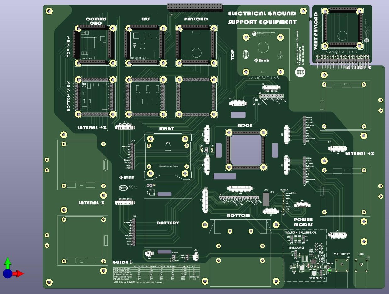 Fig1. EGSE 3D view
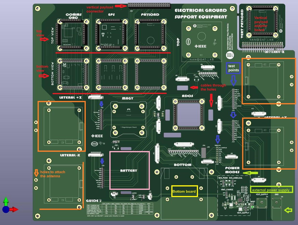
Fig2. EGSE 3D view annotations
- Red: COMMS/OBC, EPS and PAYLOAD placements. There are two sockets that allow top or bottom view,
the position can be set following the printed footprint on the board. On top right there is a small board adaptor that
can be split off the EGSE and used to place the payload in vertical position pointing outwards to deploy any antenna
if needed. The vertical payload connector is on top center of the EGSE. There are also some holes on the board that
permit to pass through the cables on the ADCS, the position of the ADCS should be attached under the EGSE with
the picoblades connectors facing downwards so that the ADCS components can be seen from above. - Blue: Available test points, on the top left boards the pins of the top or bottom position can be used as a test point
when not used. - Orange: LATERAL board placement, it has extra holes to attach the slider printed part. Also, two extra holes on
the edge to attach the cable of the antenna and test the deployment. - Pink: Battery location, it has two extra holes to be able to attach it to the EGSE with zip tie or others.
- Yellow: BOTTOM board location, it has extra holes to attach the slider printed part.
- Green: External power supply, it has bananas and the jumpers to select the power mode.
Power section
Description of the power management options of the EGSE.
The EGSE allows using the PQ with its own battery and solar cells but also permits to use an external power with several configurations. The EGSE interfaces the external power supply with some protections (overcurrent, overvoltage and reverse polarization) and uses the battery charger or backup and the EPS voltage regulator to mirror the power management of the PQ. The available modes are described in Table 1.
| Power Mode | Description |
| ONLY CHARGING BAT | If it's only necessary to charge the battery on the same conditions of the PQ and the power on the PQ it's not needed |
| ONLY POWERING PQ | Use of the PQ with the external power source, but without charging the battery. |
| ONLY POWERING MCU | Mode to program the MCU without charging the battery or using the other subsystems. |
| POWERING BAT AND PQ | Nominal mode of the PQ, but using an external power source. |
| MPPT EXTERNAL POWER | Mode that allows to simulate the power of the solar cells with the external power source. Connect the MPTT EGSE pin to the pin on the EPS board directly with a long cable. |
| PQ NORMALLY USED | Without using an external power source, mode nominal of the PQ using the battery and solar cells, the external power is isolated of the PQ. |
Table 1. Power modes description
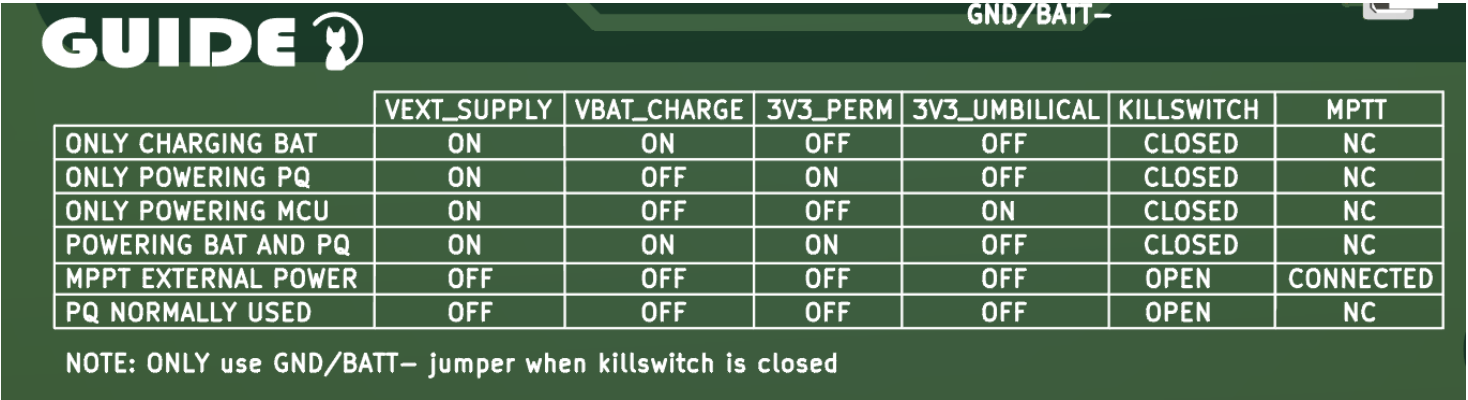
Fig3. Jumper position power modes EGSE

Fig 4. Physical position of the jumpers on the EGSE
No Comments