Killswitches
The satellite has 2 killswitches located on the bottom PCB. These are connected in series, allowing for redundancy in case one of them fails.
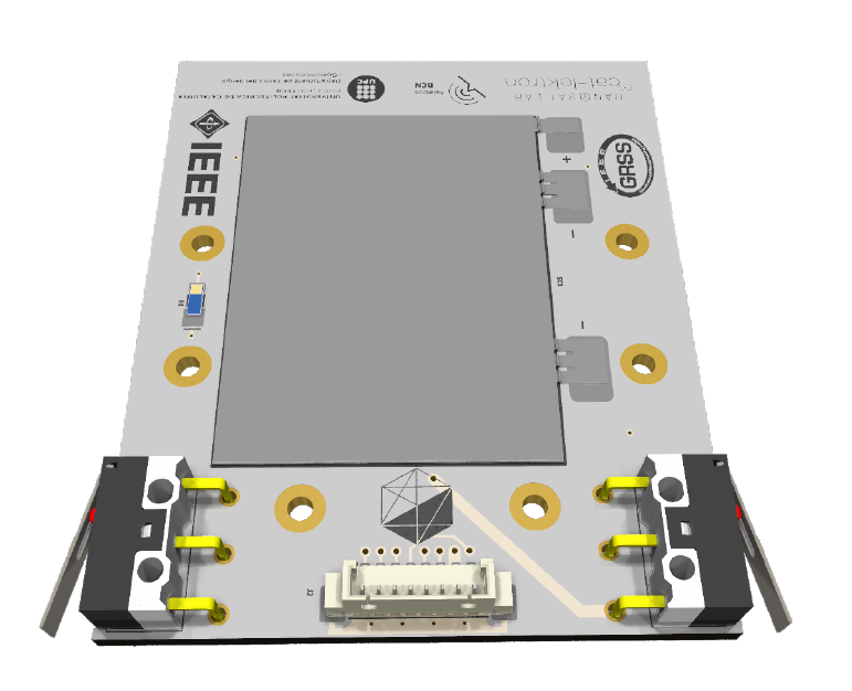
Figure 1: Killswitches in Bottom PCB
During operations where the satellite needs to be disconnected, the switches should be pressed. When the satellite is inside the deployer rail, the switches will be pressed, keeping the satellite off. Once in space, the deployer rail will release the switches, turning the satellite on by releasing the killswitches. The location of the killswitches follows the PocketQube standard [PQ Standard Alba] recommendation, positioned on the bottom PCB, just below the direct contact area with the deployer rail.
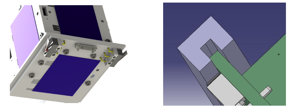
Figure 2 and 3: Killswitches Close Look and PQ Standard Killswitch location
If we analyze the general electrical scheme of the satellite in figure 4, we can see that both killswitches interfere in the direct battery line. This allows that while both are pressed, the battery will not connect to the satellite, keeping it turned off. However, the solar cells will remain connected to the EPS, and with a sun simulator or sunlight, even under AM1.5 (air mass coefficient defines the direct optical path length through the Earth's atmosphere) conditions, the satellite could be started. Therefore, it is necessary to prevent sunlight from reaching the solar cells while the killswitches are pressed.
If we analyze the general electrical scheme of the satellite in figure 3.66, we can see that both killswitches interfere in the direct battery line. This allows that while both are pressed, the battery will not connect to the satellite, keeping it turned off. However, the solar cells will remain connected to the EPS, and with a sun simulator or sunlight, even under AM1.5 conditions, the satellite could be started. Therefore, it is necessary to prevent sunlight from reaching the solar cells while the killswitches are pressed. This is a current design flaw that is under revision and awaiting further updates after design changes.
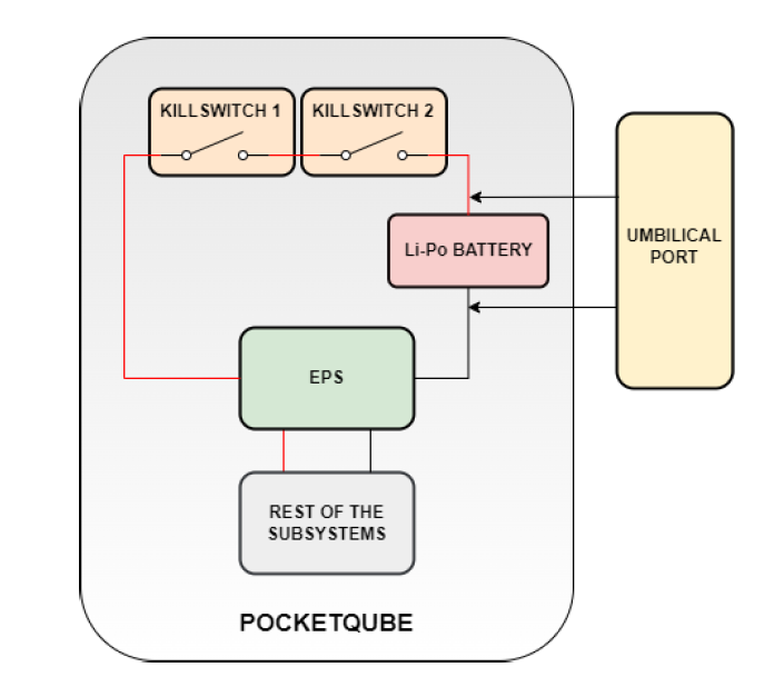
Figure 4: General Electric Scheme of the satellite with the killswitches and umbilical port
It can be observed that, even though the kill switches are pressed, the satellite still has a direct connection to the umbilical port, allowing communication with the satellite as well as the ability to charge the battery through the umbilical port.
Once the satellite is placed in the deployer rail and the kill switches are engaged, the battery will remain in standby mode, meaning it won’t charge or discharge actively. However, this will lead to a slow, passive discharge of the battery over time.
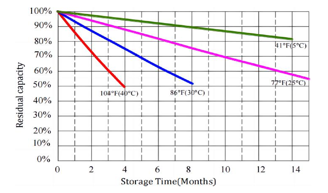
Figure 5: Capacity Discharged vs Storage Time and Temperature
According to the manufacturer’s data (figure 5), the rate of discharge depends on the temperature and how long the battery remains without the ability to charge. While these values are theoretical, in practice, the actual discharge rate can vary due to several factors. Nonetheless, these estimates provide a general idea of how long the satellite’s battery can remain without charging.
No Comments