Software Design
The software of the Attitude Determination and Control System (ADCS) is equally essential for the satellite’s operation. Without it, the satellite would lack the intelligence to interpret critical data about its orientation and respond to its environment in space, which is necessary for executing various functions. The ADCS software processes sensor data, executes algorithms to determine the satellite's position, and issues commands to control and stabilize its orientation. This ensures that the satellite can reliably carry out mission objectives such as precise data collection, alignment with targets, and consistent communication.
Attitude determination
The attitude of the satellite is represented mathematically as the rotation matrix, which stores the information about the orientation of the satellite. The objective of the ADCS is to calculate that matrix and later conduct some functionalities to achieve the desired orientation.
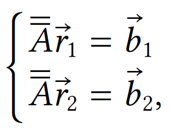
To calculate the rotation matrix, the idea is to obtain two type of vectors, each one of them represented in two different frames, the ECI and the body frame. Once we obtain these vector the following system of equations shall be solved :
 where subscript 1 represents the first vector, subscript 2 represents the second vector, r denotes the reference frame, and b denotes the body frame and the symbol A refers to the rotation matrix. Since this system of equations is undetermined, the rotation matrix cannot be directly computed and must be estimated. In order to estimate it, the TRIAD algorithm will be used.
TRIAD algorithm
The TRIAD algorith is based on the assumption that one of the unit vectors is much more accurately determined than the other. It denotes that 𝐛𝟏 is much more accurated than the others. The estimation of the rotation matrix is shown in,
Vector election criteria
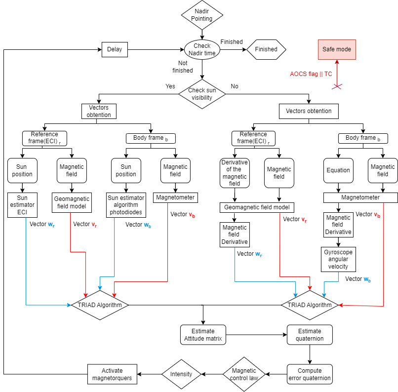
The criteria chosed to select the vectors is the following one:
- The first case is when we have Sun exposition. In this case we will use the magnetic field vector and the Sun position vector. From the magnetic field vector, the body frame vector will be obtained from the magnetometer, and the reference frame vector will be obtained by the geomagnetic field model. In terms of the Sun position vector, the body vector will be estimated using the photodiodes and the temperature sensors of the PQ. The vector from the reference frame will be obtained by an ECI Sun estimator algorithm.The first case is when we have Sun exposition. In this case we will use the magnetic field vector and the Sun position vector. From the magnetic field vector, the body frame vector will be obtained from the magnetometer, and the reference frame vector will be obtained by the geomagnetic field model. In terms of the Sun position vector, the body vector will be estimated using the photodiodes and the temperature sensors of the PQ. The vector from the reference frame will be obtained by an ECI Sun estimator algorithm.
- The other case is used when there is not direct exposition to the Sun, i.e when there is eclipse. In this case the magnetic field vector is used like in the previous case, however as the second vector we will use in the reference frame the derivation of the magnetic field and for the body frame the vectorial product between the angular velocity with the magnetic field plus the derivative of the magnetic field will be used.
Attitude Control
ADCS Mode definitions
The former AOCS modes of operations available in the PocketQube are the Detumbling mode, Nadir pointing and the IDLE mode. The primary purpose of the ADCS implementation is to prevent unnecessary energy consumption. If no AOCS functions are needed, the task will remain blocked until required, it will be activated by the onboard computer only when necessary.
Detumbling mode
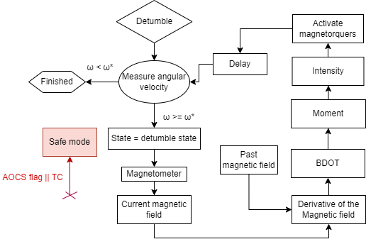
After the deployment from the rocket, the PQ is expected to start rotating at an average rate of 30 degrees per second. In addition, the PQ will be influenced by various external forces during its orbit, causing it to start rotating, and intentional rotations will be applied to the PQ to manage its temperature more efficiently. Because of these factors its necessary a functionality that permits to detumble the satellite. This mode will be used in the following situations:
- Stabilizing the satellite after its deployment.
- Stabilizing the satellite after conducting the tumbling functionality.
- Stabilizing the satellite in response to external orbital perturbations that could cause unwanted rotation.
The detumbling mode uses the BDOT controller. For determining the value of the constant used in the BDOT algorithm, the BDOT law method will be used, which uses the maximum magnetic moment that will be generated by the magnetorquers and the sign of the derivative of the measured magnetic field. This maximum magnetic moment is computed taking into account that the maximum intensity that the magnetorquer driver can provide to the magnetorquers is of 32 mA.
Nadir pointing mode
In order to perform correctly the measurements of the payload antenna, the PQ must be pointing to the Earth. Nadir pointing is the most crucial functionality of the ADCS, because it is the responsible of pointing the satellite to the Earth. For achieving it a magnetic control law is used. It computes the desired magnetic moment using the magnetic field, the angular velocity and the vectorial part of the required quaternion that is needed for rotating the satellite’s quaternion to the required quaternion.
where the constants 𝐤𝐩 and 𝐤𝐫 are obtained from the PID controller, and the 𝜺 represents the vectorial part of the error quaternion.
IDLE Mode
The IDLE mode is the default mode, this mode is always set whenever the AOCS is not running any functionality. In addition, this is the only mode where the On board computer will be able to block the AOCS task to prevent undesired energy consumption.
ADCS Control and determination algorithms
Geomagnetic field model
In the PocketQube, the geomagnetic field model that is implemented is a simple Tilted dipole model. This is due to memory limitations in the PocketQube. The tilted dipole is a simplified model of the IGRF13 with only two coefficients. However, if additional memory is available, the possibility of adding more coefficients will be considered.
| Inputs | Outputs |
| Geodetic coordinates | Magnetic field in ECI [nT] |
| Decimal year |
Orbital propagator
The orbital propagator used for the PocketQube is the J2 orbital propagator. The algorithm estimates the orbit in ECI coordinates using the TLE received from the ground station. Due to memory limitations, this propagator is chosen, but using a more accurate one will be considered if memory permits.
| Inputs | Outputs |
| Satellite TLE | Satellite propagated orbit in ECI |
| Desired propagated time [hours] |
Sun position estimator
In the PocketQube, two different methods are used to determine the sun’s position, one in the ECI frame and another in the body frame. Hence, two algorithms are implemented:
- Sun position estimator in ECI frame: This algorithm estimates the sun’s position in ECI coordinates using the Julian
date.
| Inputs | Outputs |
| Date | Sun position ECI |
- Sun position for body frame:This estimator uses photodiodes placed on the lateral, bottom, and top boards
of the satellite to determine the sun’s position relative to the satellite. The selection of the face receiving the
most sun power is based on two criteria:
- The photodiode on the face must generate current from a light source.
- If two orthogonal faces receive light (due to Earth’s albedo), the face with the highest temperature is selected.
| Inputs | Outputs |
| Received light from photodiodes | Sun position in body frame |
| Temperature of latera, bottom and top boards |


No Comments