Photodiodes Temperature Characterization
Test Description and Objectives
The main objective of this test is to characterise the temperature behaviour of the photodiode and calibrate its results.
Test Set-Up
- ADCS board and the PocketQube lateral boards.
- Multimeter, alligator clips ,cables and jumpers for the connection between the photodiodes and the ADCS board.
- A computer.
- Black coated box.
- An halogen bulb with its correct power source.
- Hair dryer.
Test Plan
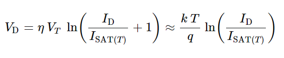
Following the Shockley Diode equation, the current coming out the photodiode depends of the temperature, following an exponential function.
The Shockley diode equation is the following one:
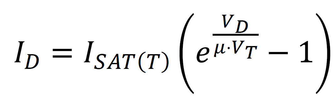
Where:
ID is the diode current.
Isat(T) is the reverse bias saturation current.
VD is the voltage of the diode.
VT is the thermal voltage.
μ is the idiality factor, it will be assumed that it is equal to 1.
In this equation there are two key parameters, the VT and the Isat(T) which are computed with the following formulas:
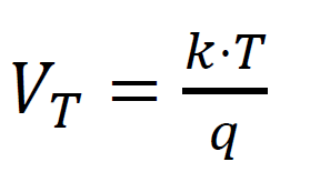
Where:
k is the Boltzman constant in [ j/k ].
T is the temperature of the diode in kelvins.
q is the elementary charge.
![]()
Where:
Tnom is the temperature in which the photodiode's characteristics are specified in the datasheet.
Eg is the energy gap.
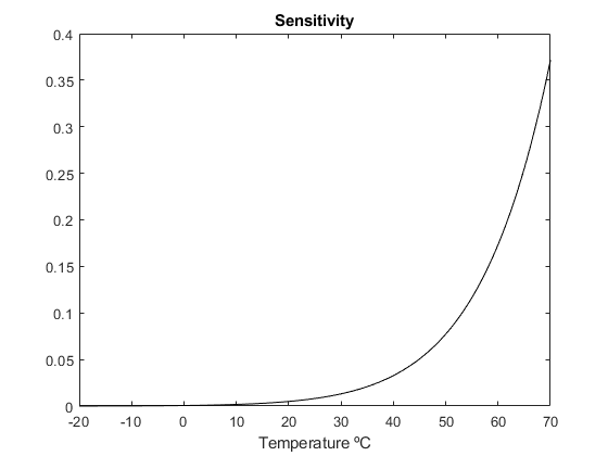
Now the next step is to derive the sensitivity equation. To obtain it, you will have to derivate the Shockley diode equation in function of the temperature:

The sensitivity in function of the temperature will have this shape:
All the parameters that has been obtained are the following:
| Computed Isat(Tnom) | Measured voltage quantized values | Measured T |
At this part of the calibration the following steps have to be followed:
- First of all, the Isat(Tnom) has to be computed. In order to do that, you have to measure the Id and Vd of the photodiode while using a constant source of light. Afterwards, isolate the Isat(Tnom) from the Shockley diode equation and compute it.
- Afterwards, put the photodiode inside the black coated box pointing towards an halogen lamp bulb. You have to take measurements of the photodiode and its operating temperature. Place the box in a place where it can reach as low temperatures as you can. While the photodiode is taking measurements, the halogen lamp will increment the temperature inside the black coated box. The temperature will increase until a maximum point, then is the turn of the dryer, start increasing the temperature inside the box pintroducing hot air little by little.
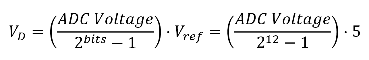
- Once the measurements are completed, the real voltage measured in the ADC can be computed, knowing that a 12-bit quantization is used.
- Next, compute the current IdI_d, considering that a resistor of 20 kΩ is being used.

- Later, compute the Vd isolating it from the Id equation:

- Afterwards, compute the sensitivity for each measurement using the sensivity equation. THe Vd and the temperature will be different for each measurement.
- The last step is to calibrate the measurements using the following equation:

![]()
Test Results
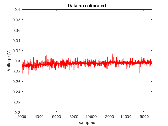
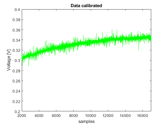
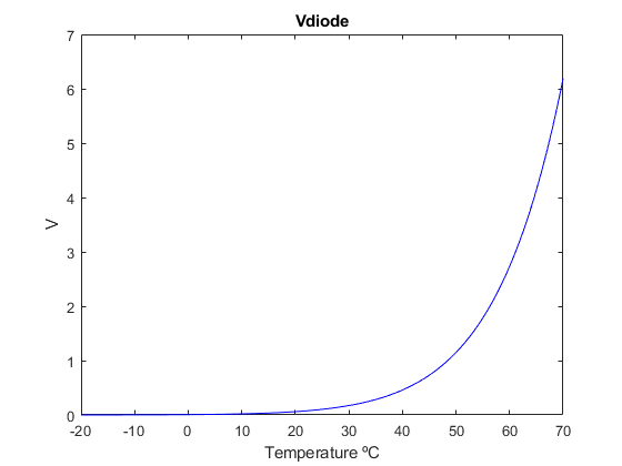
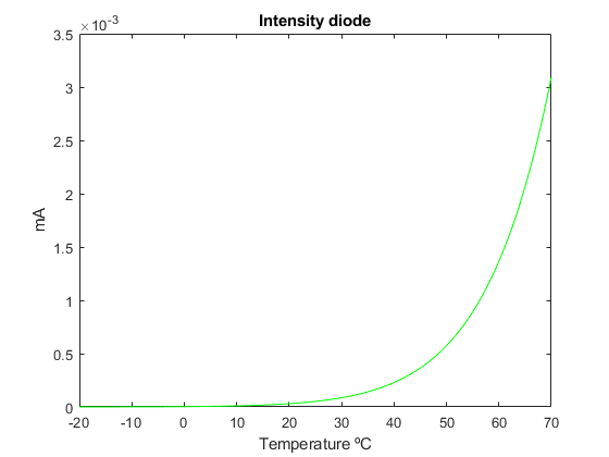
A simulation was conducted with a total of 17,000 samples of photodiode measurements taken at temperatures ranging from 15 to 35 degrees Celsius. As shown in the calibrated data, photodiode measurements increase with rising temperatures.
Conclusions
The calibration test has been conducted succesfully.
No Comments