K-Band VCO Calibration Procedure
Objective
Measure the frequency response of the VCO and characterize it.
Steps to follow
-
Turn on equipment
- Spectrum analizer
- Power supply
-
Configure to desired parameters
- Spectrum analizer
- Set center frequency in the middle of VCO output band (6250MHz)
- Set span to match the VCO output band (1400MHz)
- Set RBW and VBW to an adecuate level
- Power supply
- Set Voltage to 3.3V
- Set current limit to 0.3A
- Spectrum analizer
-
Set up nucleo board and PC
- Make sure the proper code is loaded into the nucleo board
- Set up PuTTy
- Select the serial port terminal
- Set Speed(baud) to 115200
- Set data bits to 8
- Set stop bits to 1
- Turn off parity
- Set flow control to XON/XOFF
- Set COM port to the nucleo connected one
-
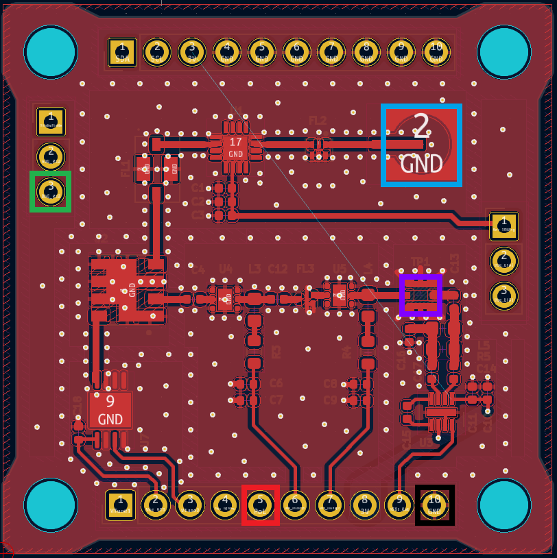
Make connections
- Connect the power supply to the payload:
- Vcc to PoL (RED)
- GND to GND (BLACK)
- Connect the DAC output to the DAC_In (GREEN)
- Connect the spectrum analizer to the switched measuring pin (PURPLE)
- Connect PC to ground (plug in the charger)
- Connect necleo board to computer by USB
- Connect the power supply to the payload:
-
Power on power supply
-
Begin the measurements procedure
- Enter frequency in PuTTy (begin on 5600 MHz)
- Measure where the input signal peak is and annotate it
- Annotate the deviation observed
- Repeat these steps with Fvco += 50 MHz
-
Update the VCO calibration and check it. If it’s not correct repeat the previous step
