Subsystem Verification
Camera testing
How to take and extract an image
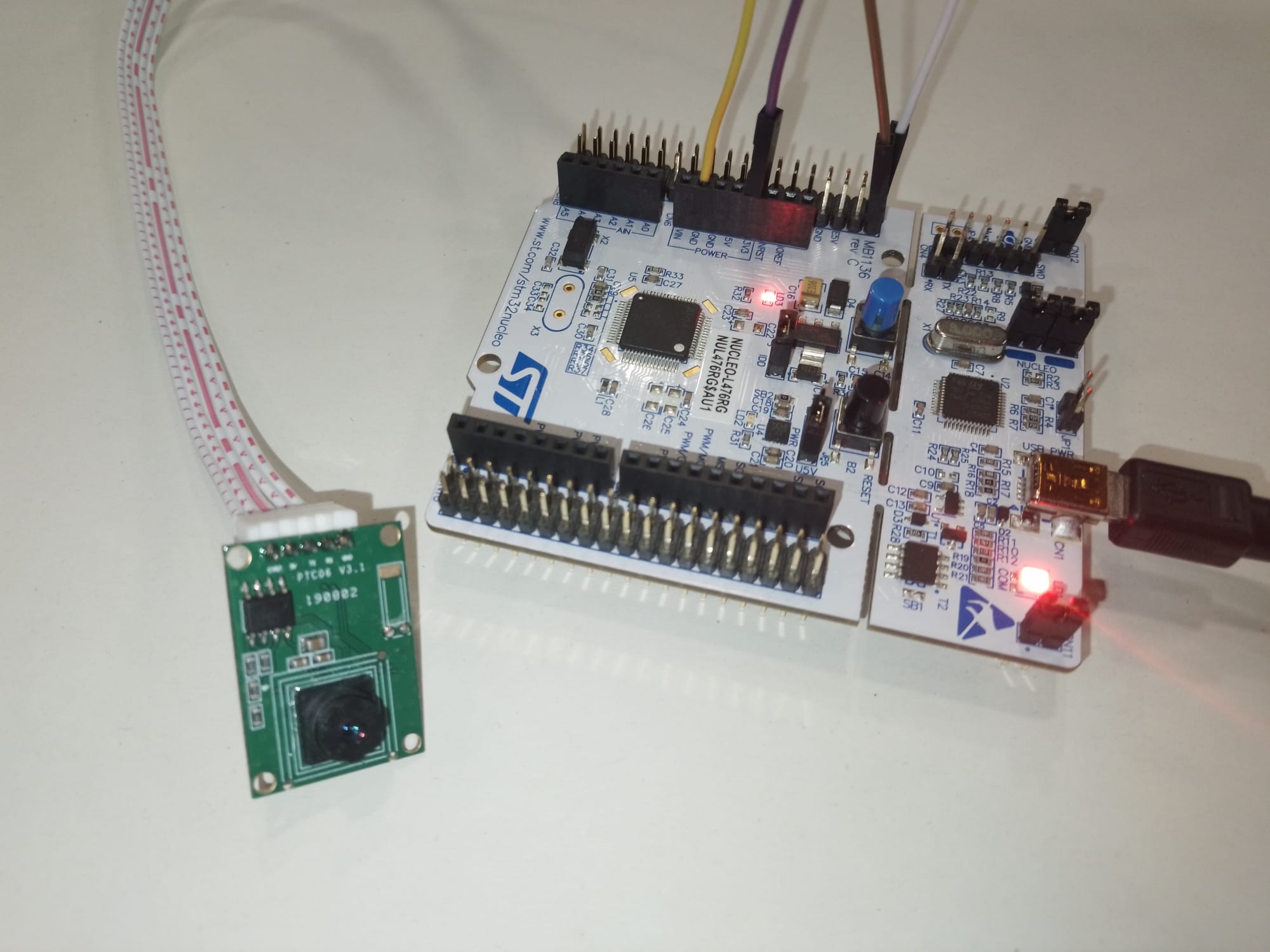
In order to take a photo the PTC06 and a STML4, which will be replaced by the OBC-COMMS board in due time, must be connected appropriately. The camera must be provided with a voltage of at least 3.3V to be in working conditions yet it'll work under 5V. A picture of the set-up is provided as well with a diagram which indicates connections to the board.
The following connections must be made between the PTC06 and the STM32:


Now that the 4 terminals are properly connected the next step is to open the STM32 IDE, and debug the project. Before resuming the debug process it is heavily suggested to check for the variable 'imlenght' in the expression viewer as well as 'camState' in the variable expression viewer, so as to know if the process is done.
Resume the debugging and wait until the camera state goes to 'CAM_STOP_CAPTURE', now check the hex length of the picture (indicated by the value of the variable 'imlenght') and exit the debug session. Now open ST-LINK Utility and enter the address where the pictures is stored (0x08040000, per default in our code) and the size of the picture (should be something along the lines of 0xAAAA). Then connect to the device and save the data as a jpg file. Note that the data should have a D8 byte in the first line and a D9 in the last one.

Obviously this is not an appropriate process to extract pictures from the payload, as it should be done remotely. As of today images can be extracted via COMMS following a Rx-Tx, but this is out of the scope of this document, as taking the picture and storing it appropriately is our only concern for now.
TEST 1: Image size-quality evaluation
As is to be expected it is necessary to evaluate the trade-off between picture size and quality of an image. So, the goal of this test is to find the most appropriate resolution/compression values considering power and data budget constraints, as we probably won't be able to send full high resolution pictures in a single pass.
Memory size with different values of resolution and compression:


![]()
![]()


It is complex to assign optimal values to resulution and compression as both can be situational depending on the enviroment that is going to be photographed. Despite this, the trade-off between compression and size is noticeably interesting in higher resolution images. When resolution decreases increasing compression seems to have a less impactful effect, both in image quality and in image size.
It is proposed to adjust both of these parameters according to the situation via telecommands.
TEST 2: DMA IMAGE TAKING
Test Description and Objectives
The objective of this test is to verify the implementation of Circular DMA in the data acquisition system of the camera.
Requirements Verification
| Requirement ID | Description |
|---|---|
| DIT- 01 | Run the proposed code without errors. |
| DIT- 02 | Take the highest quality image possible by the camera. |
| DIT- 03 | Extract the data successfully from the flash memory of an STM32 Nucleo. |
Test Set-Up
Materials
- Nucleo L476RG
- PTC06
Setup
Prepare the set-up as explained in [1].
Pass/Fail Criteria
If the stipulated conditions are fulfilled, specifically, the image is taken without the appearance of significant artefacts the test will be considered successful.
Test Plan
Step 1: Debug and run the code
It is expected to save the image in the specified address and extract the length of it during this process.
Step 2: Extracting the image
Using ST-LINK Utility we extract the corresponding image using the aforementioned length.
Step 3: Inspect the image
Inspect the image for possible artefacts and other errors.
Test Results
Step 1:
The image was not flashed in the memory in first instance. This was due to the complexity of flashing the data using another task while DMA doesn't stop receiving until a transaction is done or half done. The work-around for this issue was to implement a new data-flashing function which didn't rely on the FLASH TASK of the OBC and didn't need the copy the data stored before we started flashing.
Step 2:
The image was successfully extracted.
Step 3:
Sometimes the images appear to have significant artefacts, heavily impacting low resolution images, yet this error has been found to be random, as without any change of parameters an image is taken successfully in one run and quite affected in another one.
 Example of a high resolution image taken when errors occur.

Example of a medium resolution image with artefacts.

The same image taken instants later without any modifications.
Conclusions
DMA transfer has been successfully implemented as images can be taken without the appearance of significant errors. Despite this, it is true that some impactful errors do occur at random. Further revision into this phenomena is required as well as the implementation of a more reliable EDAC.
During the test it has been uncovered the difficulty to flash images into the memory using the FLASH TASK. We do have to remember that this task was designed and implemented to avoid memory overflow when no more stack size could be given to tasks, and as overflow hasn't occurred, the implementation of the new function might not be detrimental or needed to revisit.
TEST 3: VGA PCB - NUCLEO
Test Description and Objectives
The objective of this test is to verify the implementation of Circular DMA in the data acquisition system of the camera.
Requirements Verification
| Requirement ID | Description |
|---|---|
| VPN- 01 | All connections are well made, both inside the PCB and to the Nucleo. |
| VPN- 02 | Take an image with the camera. |
| VPN- 03 | Extract the data successfully from the flash memory of an STM32 Nucleo. |
Test Set-Up
Materials
- Nucleo L476RG
- VGA PCB
-
PCBite Kit
- Multimeter
Setup
Prepare the set-up as explained in [1], but with the connections from the VGA to the Nucleo done with a PCBite Kit or soldering. Other approaches might also be taken.

Image of our setup
Pass/Fail Criteria
If the stipulated conditions are fulfilled, specifically, the taking of an image, the test will be considered passed.
Test Plan
Step 1: Connect the PCB to the Nucleo
Making use of a PCBite or other means of connection it is checked that all pins, both from the PCB and from the VGA are successfully connected.
Step 2: Take an image
It is expected to save the image in the specified address and extract the length of it during this process.
Step 3: Extract the image
Using ST-LINK Utility we extract the corresponding image using the aforementioned length.
Test Results
Step 1:
All the connections were tested with a multimeter successfully.
Step 2:
The image was successfully taken.
Step 3:
The image was successfully extracted.

Image taken by the P/L.
Conclusions
The PCB is working normally, without any potential issues and the P/L is functional. The test is considered successful.
TEST 4: VGA-COMMS (+VGA-OBC)
This test is explained and performed in the COMMS SSV Section the of the wiki. Passed successfully. This test was performed with an individual PTC06, and will be tested with a PCB as integration advances.
TEST 5: VGA-OBC-EGSE
Test Description and Objectives
The objective of this test is to take an image integrating the OBC, VGA and EGSE systems.
Requirements Verification
| Requirement ID | Description |
|---|---|
| VOE- 01 | Take an image with the camera. |
| VOE- 02 | Extract the data successfully from the flash memory of the OBC. |
Test Set-Up
Materials
- OBC-COMMS PCB
- VGA PCB
-
EGSE (FlatSat)
Setup
Prepare the set-up as explained in [1], but with the connections from the VGA to the Nucleo done with a PCBite Kit or soldering. Other approaches might also be taken.
Pass/Fail Criteria
If the stipulated conditions are fulfilled, specifically, .
Test Plan
Step 1: Connect the PCBs to the FlatSat
Step 2: Take an image
It is expected to save the image in the specified address and extract the length of it during this process.
Step 3: Extract the image
Using ST-LINK Utility we extract the corresponding image using the aforementioned length.
Test Results
Step 1: Connections appear stable
Step 2: Image is not taken by the camera
No communication is established between the OBC and the P/L.
Step 3: -


Conclusions
The test has failed, as an image hasn't been able to be extracted. It has been found that the PTC06 on the VGA PCB used was not working properly and the test has to be redone with a new one resoldered. The previous test written before this one was made with a new resoldered camera and this test remains to be redone.
No Comments