Tests as Run
Test Description and Objectives
The objective of these tests is to check the correct functioning of the EPS system in all its parts, to ensure correct management of the energy between the solar panels and the battery to ensure the correct management of the supply in the different subsystems.
This document is based on current but also previous versions both of hardware and software and as such be followed with care.
Main components
- MPPT block > SPV1040TTR
- Battery charge/discharge management > LTC4040EUFD#PBF
- Sensor battery > DS2782E+
- Voltage regulator 3.3V > ISL9120IRTNZ
- MOSFET > SIR424DP-T1-GE3
- LiPo Battery > DNK 103438
- 1600 -> LP103740 3.7V 1600mAh https://lipolbattery.com/LiPo-Battery-1000mAh+.html
- Datasheet and 3D model of our Lightricity s3040_CIC solar cell > https://satsearch.co/products/exa-solar-cells-30-40
EPS board soldering test
Test Description and Objectives
The objective of this test is to check all the components of the EPS board to ensure the correct connectivity of every component because solder SMD components it’s a little hard to visually analyze, for that reason we need to find some specific point that help us to ensure the connections
Requirements Verification
| Requirement ID | Description |
| EPS_reqBST00 | Check visually or with microscope some short-circuit or some pin without enough tin |
| EPS_reqBST10 | Check if all IC are orientated properly |
| EPS_reqBST20 | Check if there are continuity between (Vcc) & (GND) and (Killswith+) & (Batt-) |
Test Set-Up
- EPS completetly soldered
- Multi-meter with wires
- PC with KiCAD with the EPS project opened
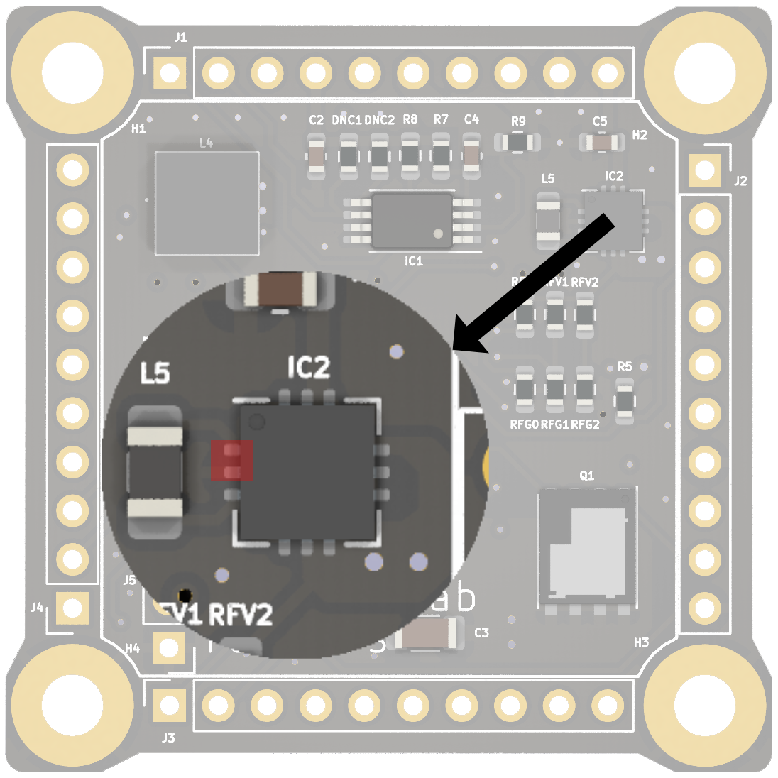
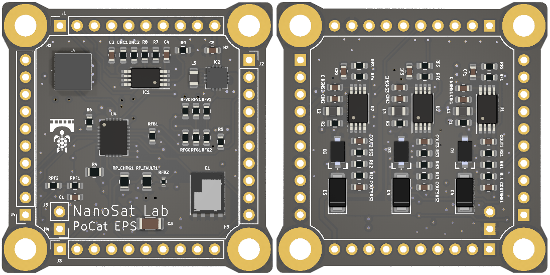
First, to verify EPS_reqBST00 and EPS_reqBT10, we need to visually inspect the components, paying particular attention to checking for potential short circuits or tin bubbles. We especially focus on U4 (LTC4040), Q1 (SIR424DP), and IC2 (ISL9120IRTNZ).
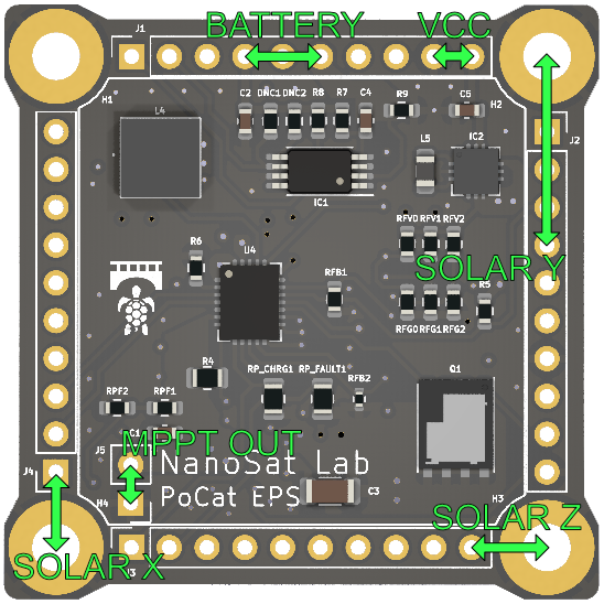
We will check the input of the MPPTs, their output, the battery power input, and the EPS output, to ensure there are no short circuits
If we encounter a short circuit during any of these checks, we should search for and repair the issue. To do this, we will return to step EPS_reqBST00 and attempt to resolve the short circuit. Pay attention to any potential tin bubbles that may have remained between the pins of the ICs
Pass/Fail Criteria
This test will be considered passed if all the requirement verifications are completed successfully
If one of the requirements fails, we cannot consider the test passed. For the following steps, where we apply voltage to the ICs, we need to ensure that there are no short circuits and no visible soldering errors to avoid damaging the PCB
Test Plan
| Step ID | Description | Pass/Fail Criteria | Actual | Passed\[Y/N\] |
| EPS_testBT00 | Solder all EPS board |
Ensure to solder the correct components in the correct places |
EPS components have been soldered properly | Y |
| EPS_testBT10 | Visually inspect the soldering | Check for any solder bridges between pins that could cause a short circuit or any poorly soldered pins | Some pins with short circuits were found and resolved, and some tin bubbles were removed | Y |
| EPS_testBT20 | Check electrically for short circuits | If we confirm the specified short circuits in the Test Set-Up, we pass the test | I had a short circuit in Solar Y due to the diode D2 being reversed. The diode has been rotated, and now it no longer indicates a short circuit | Y |
Test Results
Two short circuits caused by tin bubbles have been cleaned on IC2 and one on the U4, which have finally been eliminated.
An error was made in the placement of a component in step EPS_testBT00, which we initially deemed as good. We overlooked the polarity detail. The diode was rotated, and with this, we can confirm that the short circuit has been eliminated.
Anomalies
No anomalies have been detected.
Conclusions
We have been able to verify that there are no short circuits in the EPS, so the first EPS board soldering test has been passed. Now, the next test will involve applying voltage, so it is important to ensure that there are no short circuits-
EPS Battery and MPPT Evaluation
Test Description and Objectives
The purpose of this test is to verify that the EPS functions correctly electrically by powering it in different ways and checking that the outputs are as expected. Prior to this, we check for any short circuits, so now we can safely power it knowing that there are no short circuits. However, this does not mean that there are no errors, and therefore, we could potentially damage a chip. That's why it's important to have thoroughly checked the PCB in the previous test to minimize the risk of damaging any components.
Requirements Verification
| Requirement ID | Description |
| EPS_reqBT00 | Verify that we can obtain a constant 3.3V output from the EPS using a power supply |
| EPS_reqBT10 |
Verify that we can obtain a constant 3.3V output from the EPS using a battery |
| EPS_reqBT20 | Check that the MPPTs function with a power supply |
| EPS_reqBT30 | Verify that the MPPTs function with the solar cells |
| EPS_reqBT40 |
Verify that we can obtain a constant 3.3V output from the EPS using the MPPTs and the solar cells |
Test Set-Up
- EPS completetly soldered
- Multi-meter with wires or osciloscope with probe
- Power Supply
- LiPo Battery
- Lighttricity solar cell
- Wires
First, we are going to desolder diodes D4, D5, and D6 in order to separate the MPPT from the rest of the electronics.
We are going to set the power supply to 3V and limit the current to 0.1A.
To test the MPPT, we need to connect the solar cells on the top side and perform measurements on the bottom side. The GND of the solar panels must be connected to the PCB GND
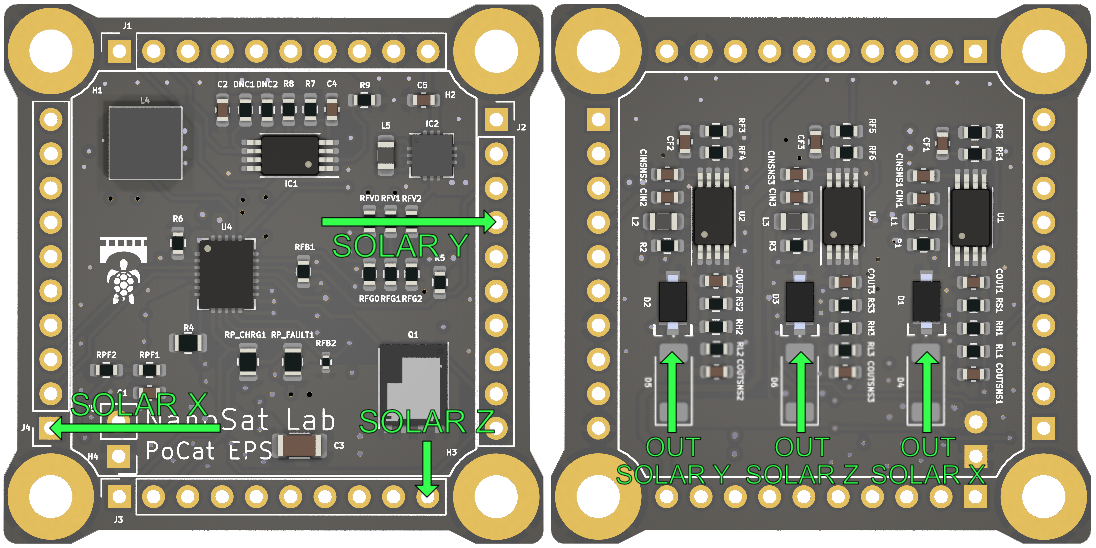
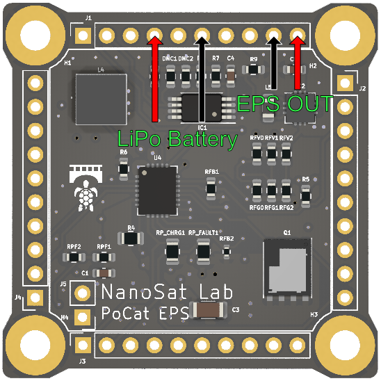
Then to test EPS with the battery, it's important to connect the battery in the correct location. We must not connect the battery negative to the GND, as they are not the same. The battery negative should go to the BATT-. The output of the EPS is the 3.3V output that will be seen by the other SSVs
Pass/Fail Criteria
This test will be considered passed if all the requirement verifications are completed successfully
If one of the requirements fails, we cannot consider the test passed, as this process is important to ensure the correct power supply for the other SSVs
Test Plan
| Step ID | Description | Pass/Fail Criteria | Actual | Passed\[Y/N\] |
| EPS_testBT00 | Apply between 2V and 3V to the input of Solar X and check the MPPT operation | Output Solar X should have a voltage higher than the input, around 4V | The output is 4.5V, therefore we can confirm that the MPPT is functioning | Y |
| EPS_testBT10 | Apply between 2V and 3V to the input of Solar Y and check the MPPT operation | Output Solar Y should have a voltage higher than the input, around 4V | The output is 4.6V, therefore we can confirm that the MPPT is functioning | Y |
| EPS_testBT20 | Apply between 2V and 3V to the input of Solar Z and check the MPPT operation | Output Solar Z should have a voltage higher than the input, around 4V | The output is 4.6V, therefore we can confirm that the MPPT is functioning | Y |
| EPS_testBT30 | Apply 4V from the power supply to the battery input (KillSwitch + and Batt -) | Check if we have a constant 3.3V output at the EPS (VCC and GND) |
The output is not 3.3V, so the battery regulator part is not working. Additionally, there is a slight whistle coming from the EPS |
N (6.1) |
If we pass all the tests, we will resolder diodes D4, D5, and D6 to test the MPPT with the rest of the power management circuit and repeat the test to ensure the correct functioning of all EPS components with MPPT and power management together.
Now, the output pins for testing the MPPT blocks will be the EPS OUT instead the Solar OUT because we have added the diode, which makes more sense. Furthermore, we will continue using the power supply to test the battery and solar components via the EPS output
| Step ID | Description | Pass/Fail Criteria | Actual | Passed\[Y/N\] |
|
EPS_testBT40 |
Apply a voltage between 2V and 3V to the input of Solar X and check if the output works with only this power input when we illuminate it with strong light | The EPS output (VCC and GND) should provide a constant 3.3V | The EPS output provides a constant 3.3V | Y |
|
EPS_testBT50 |
Apply a voltage between 2V and 3V to the input of Solar Y and check if the output works with only this power input when we illuminate it with strong light | The EPS output (VCC and GND) should provide a constant 3.3V | The EPS output provides a constant 3.3V | Y |
|
EPS_testBT60 |
Apply a voltage between 2V and 3V to the input of Solar Z and check if the output works with only this power input when we illuminate it with strong light | The EPS output (VCC and GND) should provide a constant 3.3V | The EPS output provides a constant 3.3V | Y |
|
EPS_testBT70 |
Apply 4V from the power supply to the battery input (KillSwitch + and Batt -) | Check if we have a constant 3.3V output at the EPS (VCC and GND) | The EPS output provides a constant 3.3V | Y |
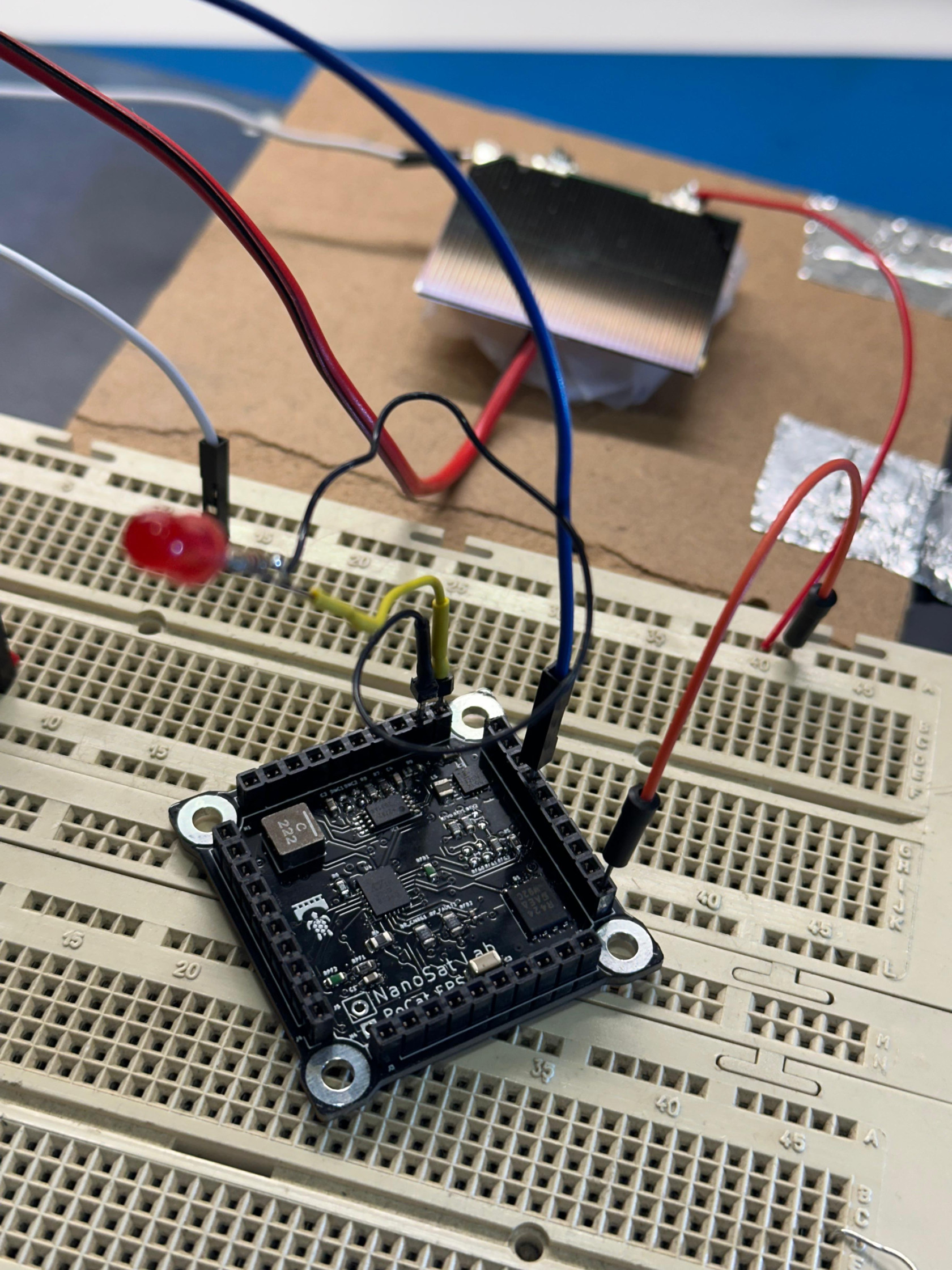
If we pass all the tests, now we will replace the power supply with solar cells and a LiPo battery. This way, we will perform the test in the real scenario
First we will connect the Lighttricity solar cells to the solar cell inputs, and then the battery (taking care with the polarity) to the pins (Killswitch+ and Batt-)
| Step ID | Description | Pass/Fail Criteria | Actual | Passed\[Y/N\] |
|
EPS_testBT80 |
We connect the Lighttricity solar cell to the Solar X input and illuminate it with strong light | The EPS output (VCC and GND) should provide a constant 3.3V | The EPS output provides a constant 3.3V | Y |
|
EPS_testBT90 |
We connect the Lighttricity solar cell to the Solar Y input and illuminate it with strong light | The EPS output (VCC and GND) should provide a constant 3.3V | The EPS output provides a constant 3.3V | Y |
|
EPS_testBT100 |
We connect the Lighttricity solar cell to the Solar Z input and illuminate it with strong light | The EPS output (VCC and GND) should provide a constant 3.3V | The EPS output provides a constant 3.3V | Y |
|
EPS_testBT110 |
Connect the LiPo battery to the battery input | Check if we have a constant 3.3V output at the EPS (VCC and GND) | The EPS output provides a constant 3.3V | Y |
|
EPS_testBT120 |
Connect a solar cell illuminated with strong light, and also connect the battery at the same time | Check that the output of the EPS remains at a constant 3.3V even when it receives sufficient energy from both inputs (solar and battery) | The EPS output provides a constant 3.3V | Y |
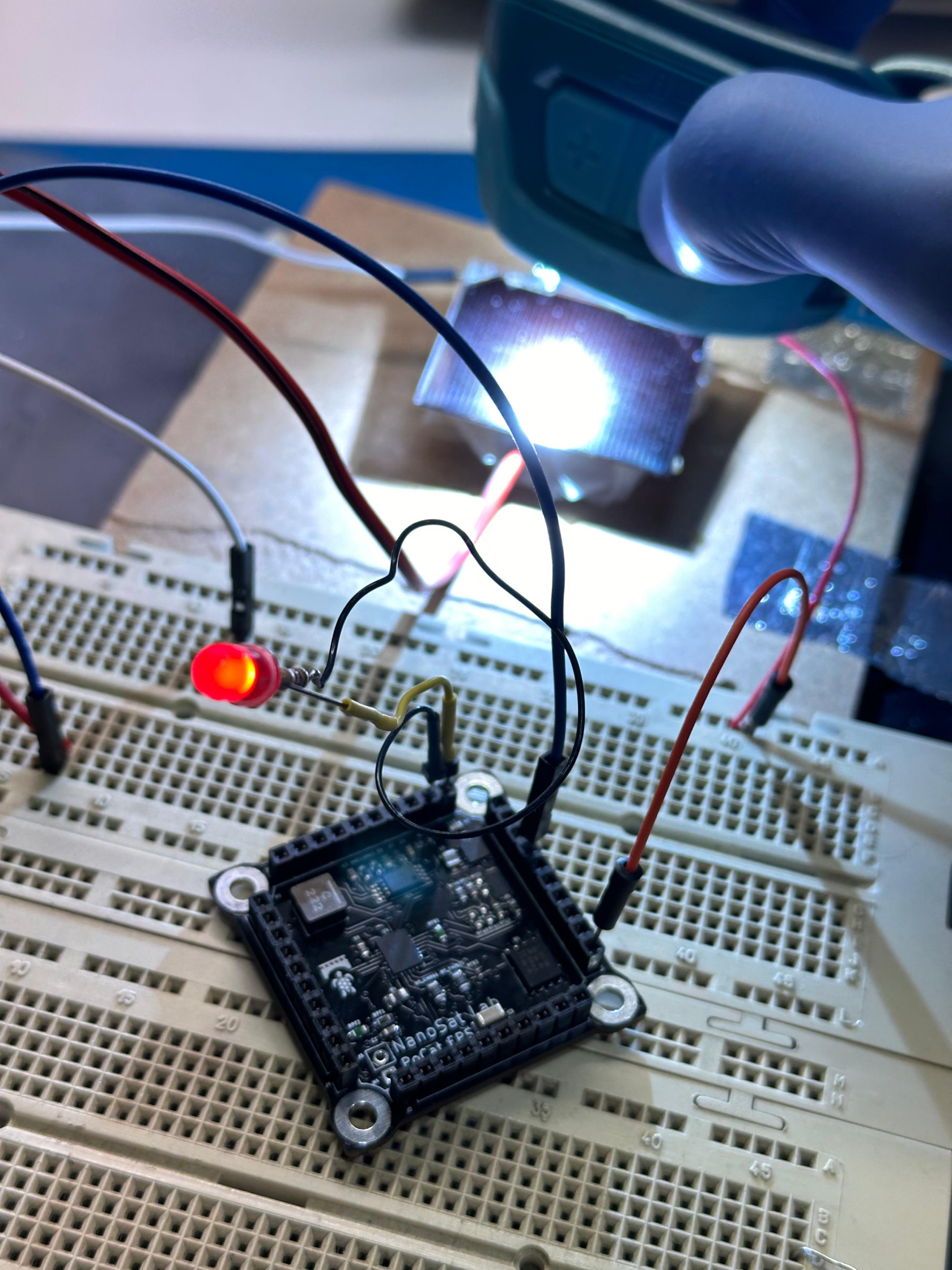
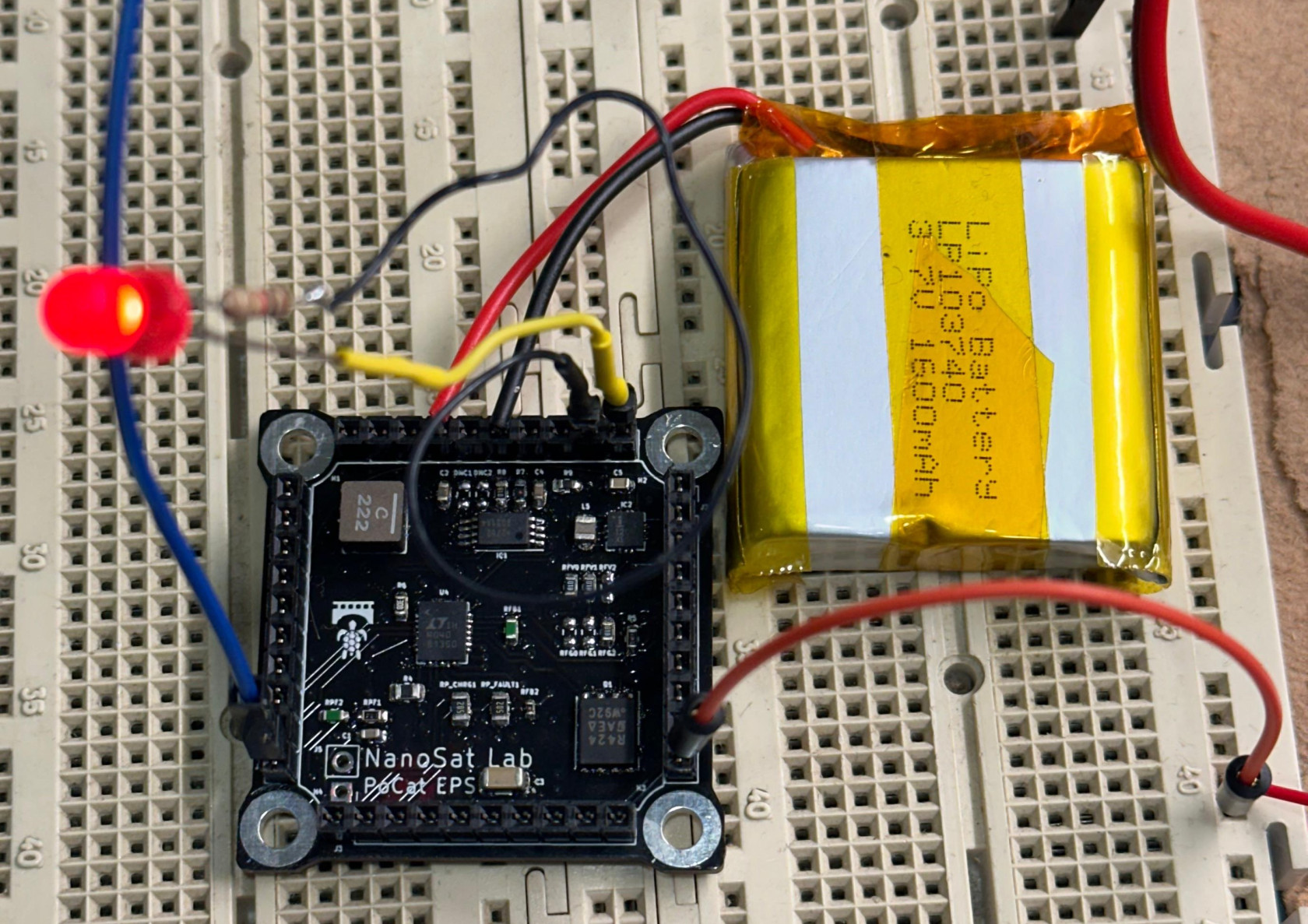
In this example, we can observe that when we connect a small load like an LED to the EPS output, the LED lights up when we illuminate the solar cell with a strong light, in this case from a headlamp
We can also see the result when connecting the LiPo battery.
Test Results
We can confirm that we are able to provide a constant voltage of 3.3V at the output of the EPS using both the solar cells and the battery. Therefore, we will be able to properly power the different SSV either by solar light or by battery
6.1 EPS_testBT30
After checking that supplying 4V from the power supply to the EPS via the battery pins does not provide the expected constant 3.3V output, and additionally hearing a slight whistle from the PCB, we will review the PCB once more to identify any possible overlooked issues or visual signals that may provide clues.
We observe that the LX2 (1) and PGND (2) pins of the ISL9120IR regulator are short-circuited, so we proceed to remove the short circuit.
| Step ID | Description | Pass/Fail Criteria | Actual | Passed\[Y/N\] |
| EPS_testBT30 | Apply 4V from the power supply to the battery input (KillSwitch + and Batt -) | Check if we have a constant 3.3V output at the EPS (VCC and GND) | The output is a constant 3.3V. | Y |
Anomalies
If we illuminate the solar cells with classroom lighting or the flash of a mobile phone, we observe that the solar cell reaches 2V but is unable to activate the MPPT, thus it does not function. We require a more powerful light source, such as a headlamp, which also generates 2V from the solar cell but provides more current. So, we should not depend solely on the voltage reading from the solar cells to determine their operational status
Conclusions
Now, we have the MPPT working with the Lighttricity cells and the battery regulator as well. Therefore, we can now proceed with the next tests, as we can confirm that the generated voltages are correct.
Battery sensor test
Test Description and Objectives
The objective of this test is to check the correct functioning of battery sensor that provides to OBC some data about the battery like the Voltage, Current and Temperature.
Requirements Verification
| Requirement ID | Description |
| EPS_reqBS00 | Be able to read the battery voltage |
| EPS_reqBS10 | Be able to read the temperature of the battery using NTC |
| EPS_reqBS20 | Be able to read the actual current value |
| EPS_reqBS30 | Be able to read the average current value of the last 28s |
| EPS_reqBS40 | Be able to read the accumulated current value |
Test Set-Up
- 1x EPS board full soldered
- 1x STM32 Nucleo board
- 1x Power supply with 2 outputs
- 1x NTC sensor
- 1x Multi-meter or something with the capability to measure temperatures
- 1x Peltier cell to generate cold/hot temperatures or air hot gun
- 4x Banana-Banana power cables
- 1x LiPo battery
First, we will connect the EPS board to the STM32 Nucleo via I2C connection, and then connect the Nucleo to the STM32CubeIDE software.
Then we connect the NTC temperature sensor on EPS board, to modify the temperature we can use a Peltier cell that if we invert polarity will give us hot or cold as we need
Into the battery connector, we can connect a real LiPo battery or power supply.
The last is connect some kind of thermometer that gives us a real measurement of the read temperature of NTC sensor to compare with it.
Pass/Fail Criteria
This test will be considered passed if all of the following actions are performed successfully:
- If the read temperature is equal to the measured with external thermometer
- If the read voltage and current readings on sensor are equal with the showed on the power supply display or with a known value
On Standby

