Subsystem Verification (SSV)
The SSV of the OBC consists of two main components: hardware and software.
Hardware Validation
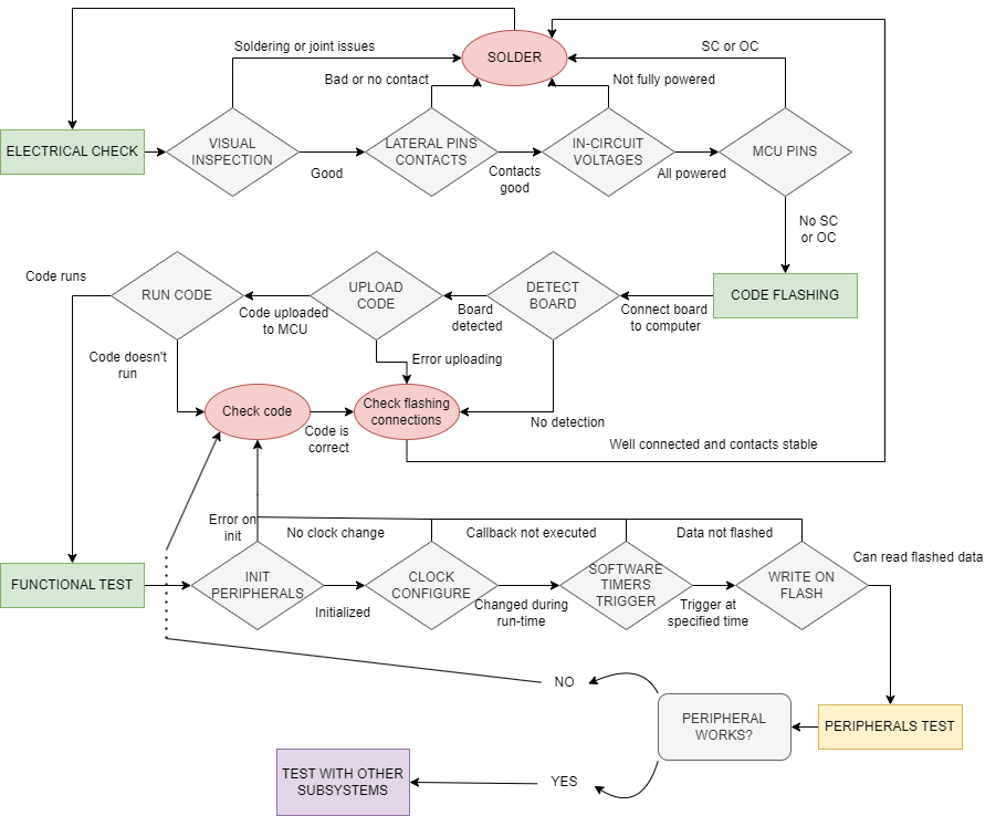
The hardware validation begins with an electrical check. The first step is to visually inspect the soldered board for marks, scratches, significant soldering errors, and other potential issues. Next, the lateral pins of the board are evaluated for poor contacts.
Once all contacts are confirmed, voltages are measured, and MCU pins are checked for potential shorts or open circuits. If the hardware is deemed properly set up, the software evaluation phase begins. It is essential to ensure that the MCU can run user-uploaded code. At this stage, new potential points of failure include the flashing connections and the uploaded code.
After successfully running simple code on the MCU, the next step is to evaluate the initialization of various mission-critical peripherals. This includes on-the-fly clock reconfigurations, which may occur during the mission, and confirming that software timer triggers occur at the specified times. It is also critical to verify that writing to flash memory is possible. Following these steps, the peripherals are tested, and integration with other subsystems is performed to further verify proper behavior.
Software Development and Validation
At every stage of software development, different strategies are employed to validate progress. The initial steps involve using a Nucleo STM L4746RG Development Board. Since most subsystems rely on the MCU and the power line, both of which can be easily emulated, the software for each subsystem is first tested on a system composed of the Nucleo and the hardware to be validated.
In the early iterations, a bare-bones approach is taken, delaying the implementation of the software into the FreeRTOS environment until the hardware is validated. Once the software is adapted and integrated into the RTOS, the unit to be verified consists of the previous hardware and the software as a single FreeRTOS task. Note that some subsystems require values read from sensors for verification. To address this, numerical approximations of these values are used to simplify testing.
Once a subsystem is confirmed not to be a source of problems, it is integrated with the actual OBC-COMMS board for further testing. This integration may be facilitated by the EGSE (FlatSAT) or through manual connections, depending on the system.
During subsequent validation phases, the unit under test expands to cover the full system or as much as is reasonably testable. This includes integrating the remaining subsystems, both in hardware and software. The modular approach of the system facilitates comprehensive verification. FlatSAT testing is crucial during this phase, as it provides a suitable platform for system-level software tests.
Final Validation Steps
The final steps involve verifying the software under the environmental conditions the satellite will encounter. This process encompasses the entire system and simulates these conditions using various facilities and tools.
To support communication with the external environment for control and debugging purposes, the satellite is equipped with two communication mechanisms. The first is an umbilical cable, which facilitates the transmission of output logs generated by the satellite and allows for command input via a wired connection. The second method utilizes RF through the communications antenna, enabling command transmission in a manner consistent with real operational scenarios.

