COMMS Antenna deployer
Introduction
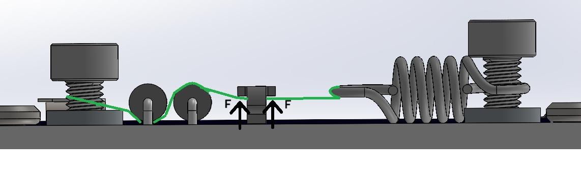
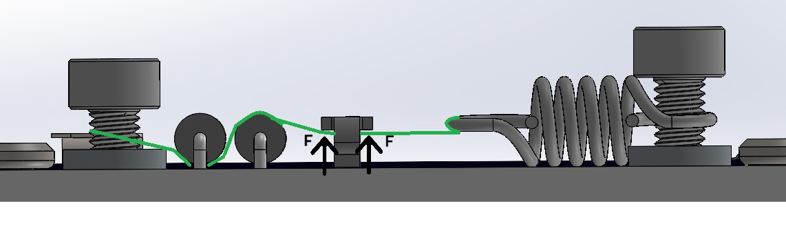
The antenna deployment mechanism will consist of two elements: a dyneema string attached to the end of the COMMS antenna, and a low-impedance resistor mounted on a lateral board. The dyneema string will wrap around the satellite as illustrated in the renders below and will be connected to the low-impedance resistor, also known as the thermal knife. The cable needs to be tensed so that the antenna cannot wiggle during the launch.


Description
The resistor is currently set at 4.7 Ohms, but further tests—including deployment in vacuum conditions—are planned to confirm its suitability. Other resistor values may offer better performance, so a trade-off analysis is needed to optimize results.
Due to the power limitations of our PocketQube, the system does not include a second thermal knife. However, the thermal knife can be activated multiple times if necessary, ensuring proper deployment.
The wire connecting the antenna to the thermal knife is a dyneema, specifically commercially used fishing wire made from polyethylene. More precisely, it is ultrahigh-molecular-weight polyethylene (UHMWPE), a material known for its remarkable properties, including extremely high tensile strength (up to 26 kg), making it ideal for high-stress environments, such as rocket launches. In terms of thermal properties, UHMWPE has a breaking temperature between 120°C and 130°C.
The antenna is made from metallic metric tape, a coated stainless steel material. One end of the wire will be secured to the antenna with a knot, while the other end will be tied to the thermal knife using a knot through the holes designed for this purpose on the lateral board. A final knot design is yet to be selected, as it will need to be validated during the vibration phase of environmental testing.
There are two inhibitors preventing the antenna's deployment:
- Physical Inhibitor: The kill switches on the satellite, which disconnect the PocketQube from the battery while inside the deployer.
- Software Inhibitor: The INIT mode, which enforces a 45-minute standby period after the kill switches are depressed, as described in the Satellite Operation Modes section.
Mechanical Integrity Calculations
The following calculations verify the mechanical integrity of the jumper during the launch phase of the PocketQube. The objective is to ensure that vertical forces acting on the component do not lead to pad failure.
 Spring Force
The axial force exerted by the spring is determined by the formula Fs = k*x. To establish a worst-case scenario for structural integrity, a total displacement of 3mm is assumed. This value accounts for a 1.5 mm installation pre-tension and an additional 1.5 mm dynamic displacement caused by launch vibrations and antenna mass.
Using the McMaster-Carr 5108N98 spring:
-
Spring Rate: 2.758 N/mm
-
Total Extension: 3 mm}
-
Resulting Axial Force: 8.27 N
Static Case
In the static configuration, the axial force is decomposed into vertical components based on the thread geometry. Due to the "pulley effect" created by the Dyneema thread passing through the jumper, the vertical load is the sum of the components on both sides:
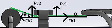
Fv1= F * sin ⍺ = 0 N
Fv2 = F * sin θ = 2.28 N
Fapplied = Fv1+ Fv2 = 2.28 N
(Angles computed as ⍺ = 0, θ = 17.75º)
At this level the component is well within its safety margin, as each pad is estimated to support up to 4.13 N.
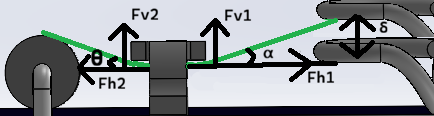
Vertical Displacement Case
The launch environment introduces random vibrations that induce lateral oscillation in the spring and a displacement that modifies the previous values.
To calculate this displacement, we first determine the lateral stiffness (as it's not provided by the manufacturer) and the resonance frequency:
Before using the method we need to compute the lateral resonance freq, using the lateral k (not provided by the manufacturer so it's aproximated)
![]()
![]()
Frequency of 188Hz won't be affected by sinusoidal vibration but can be critical in random vibration.
Using ESA's PSD profile (0.16g2/Hz at 188Hz) the following formula is used to obtain effective acceleration, and then, converted into physical distance.
![]()
![]()
Obtaining 21.7Grms and a displacement of 0.45mm
As said, during peak vibration, the dynamic displacement alters the thread angles, increasing the vertical load on the jumper.
Fv1= F * sin ⍺ = 2.7 N
Fv2 = F * sin θ = 2.28 N
Fapplied = Fv1+ Fv2 = 4.98 N
(Angles computed as ⍺ = 21.21º, θ = 17.75º)
The total vertical force of 4.98N is distributed across two solder pads. While the load per pad exceeds the static ideal, it remains within a manageable range for the Harwin S1731-46R.