# Mechanisms
# COMMS Antenna deployer
## Introduction
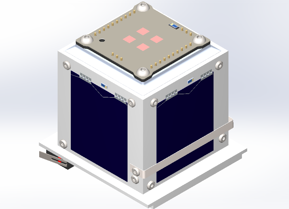
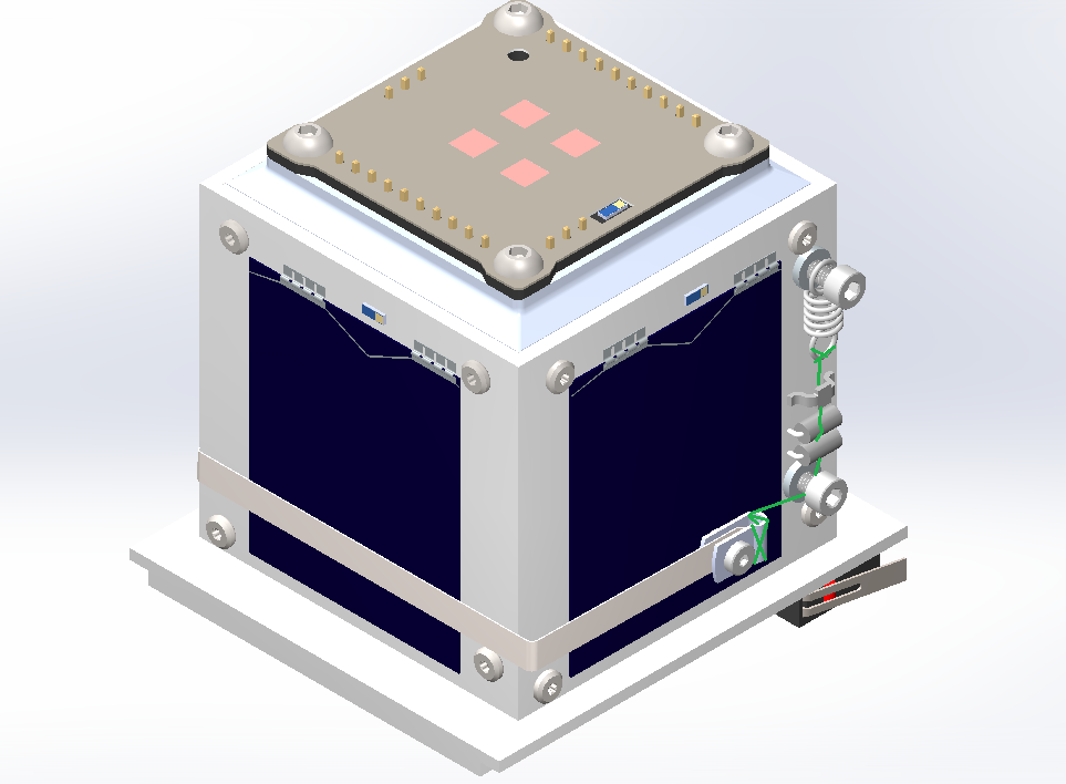
The antenna deployment system is a critical mechanical assembly designed to secure the COMMS antenna in its stowed configuration during launch and ensure a reliable release once in orbit. The mechanism integrates structural, thermal, and elastic components to achieve a fail-safe deployment.
 [](https://wiki.nanosatlab.space/uploads/images/gallery/2026-03/46limage.png)
#### 1.1 System Components
The assembly consists of the following key elements:
- Tether: A high-strength Dyneema string.
- Actuators: Two low-impedance resistors (acting as thermal knives) mounted on a dedicated lateral PCB.
- Mechanical Routing: An SMT Jumper (Harwin S1731-46R) used as a precision guide and two M2.5 screws secured with thread inserts.
- Tensioning System: A high-stiffness extension spring (McMaster-Carr 5108N98) and a cable clip attached to the antenna tip.
#### 1.2 Functional Description
The Dyneema string wraps around the satellite's perimeter, providing the primary constraint for the antenna. From its attachment point at the cable clip, the tether is routed to a primary screw that acts as a 90º pivot.
Following the pivot, the string passes directly over the thermal knives. To ensure high-reliability ignition, the SMT Jumper is positioned to provide constant downward pressure, forcing the Dyneema into direct contact with the resistors.
#### 1.3 Launch Integrity
To survive the high-vibration environment of the launch vehicle, the system must remain under constant tension. This is achieved by the extension spring, which compensates for any mechanical tolerances and prevents the antenna from oscillating or "wiggling." This tension ensures that the tether remains correctly seated over the thermal knives until the deployment sequence is initiated by heating the resistors to the tether's melting point.
## Description
The resistor is currently set at 4.7 Ohms, but further tests—including deployment in vacuum conditions—are planned to confirm its suitability. Other resistor values may offer better performance, so a trade-off analysis is needed to optimize results.
The wire connecting the antenna to the thermal knife is a dyneema, specifically commercially used fishing wire made from polyethylene. More precisely, it is ultrahigh-molecular-weight polyethylene (UHMWPE), a material known for its remarkable properties, including extremely high tensile strength (up to 26 kg), making it ideal for high-stress environments, such as rocket launches. In terms of thermal properties, UHMWPE has a breaking temperature between 120°C and 130°C.
The antenna is made from metallic metric tape, a coated stainless steel material. One end of the wire will be secured a cable clip at the antenna with a knot, while the other end will be tied to the spring. A final knot design is yet to be selected, as it will need to be validated during the vibration phase of environmental testing.
There are two inhibitors preventing the antenna's deployment:
1. Physical Inhibitor: The kill switches on the satellite, which disconnect the PocketQube from the battery while inside the deployer.
2. Software Inhibitor: The INIT mode, which enforces a 45-minute standby period after the kill switches are depressed, as described in the *[Satellite Operation Modes](https://wiki.nanosatlab.space/books/cat-introduction-requirements/page/satellite-operational-modes)* section.
## Mechanical Integrity Calculations
The following calculations verify the mechanical integrity of the jumper during the launch phase of the PocketQube. The objective is to ensure that vertical forces acting on the component do not lead to pad failure.
##### [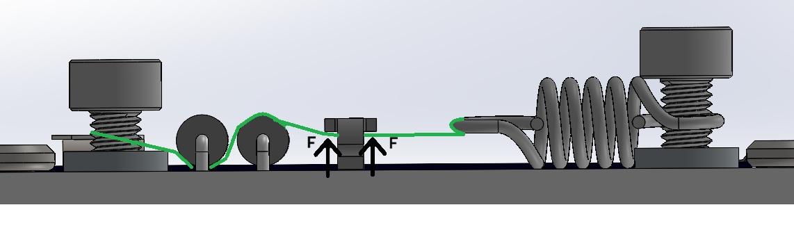](https://wiki.nanosatlab.space/uploads/images/gallery/2026-02/deploymentforces.jpg)Spring Force
The axial force exerted by the spring is determined by the formula Fs = k\*x. To establish a worst-case scenario for structural integrity, a total displacement of 3mm is assumed. This value accounts for a 1.5 mm installation pre-tension and an additional 1.5 mm dynamic displacement caused by launch vibrations and antenna mass.
Using the McMaster-Carr 5108N98 spring:
- **Spring Rate:** 2.758 N/mm
- **Total Extension:** 3 mm}
- **Resulting Axial Force:** 8.27 N
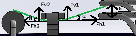
##### Static Case
In the static configuration, the axial force is decomposed into vertical components based on the thread geometry. Due to the "pulley effect" created by the Dyneema thread passing through the jumper, the vertical load is the sum of the components on both sides:
[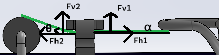](https://wiki.nanosatlab.space/uploads/images/gallery/2026-02/T41image.png)
Fv1= F \* sin ⍺ = 0 N
Fv2 = F \* sin θ = 2.28 N
Fapplied = Fv1+ Fv2 = 2.28 N
(Angles computed as ⍺ = 0, θ = 17.75º)
At this level the component is well within its safety margin, as each pad is estimated to support up to 4.13 N.
##### Vertical Displacement Case
The launch environment introduces random vibrations that induce lateral oscillation in the spring and a displacement that modifies the previous values.
[](https://wiki.nanosatlab.space/uploads/images/gallery/2026-02/98Pimage.png)
To calculate this displacement, we first determine the lateral stiffness (as it's not provided by the manufacturer) and the resonance frequency:
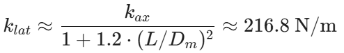 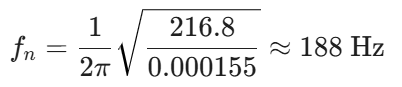
Frequency of 188Hz won't be affected by sinusoidal vibration but can be critical in random vibration.
Using ESA's PSD profile (0.16g2/Hz at 188Hz) the following formula is used to obtain effective acceleration, and then, converted into physical distance.
 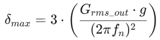
Obtaining 21.7Grms and a displacement of 0.45mm
As said, during peak vibration, the dynamic displacement alters the thread angles, increasing the vertical load on the jumper.
Fv1= F \* sin ⍺ = 2.7 N
Fv2 = F \* sin θ = 2.28 N
Fapplied = Fv1+ Fv2 = 4.98 N
(Angles computed as ⍺ = 21.21º, θ = 17.75º)
The total vertical force of 4.98N is distributed across two solder pads. While the load per pad exceeds the static ideal, it remains within a manageable range for the Harwin S1731-46R.
# Killswitches
The satellite has 2 killswitches located on the bottom PCB. These are connected in series, allowing for redundancy in case one of them fails.
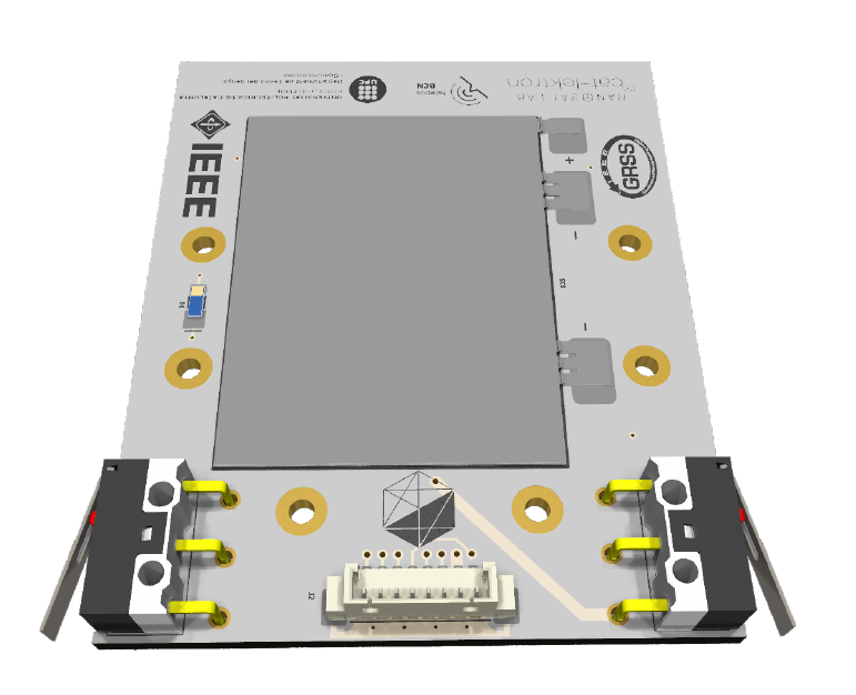
Figure 1: Killswitches in Bottom PCB
During operations where the satellite needs to be disconnected, the switches should be pressed. When the satellite is inside the deployer rail, the switches will be pressed, keeping the satellite off. Once in space, the deployer rail will release the switches, turning the satellite on by releasing the killswitches. The location of the killswitches follows the PocketQube standard [PQ Standard Alba] recommendation, positioned on the bottom PCB, just below the direct contact area with the deployer rail.
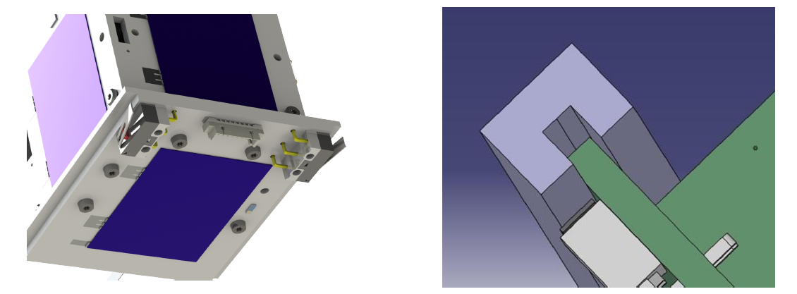
Figure 2 and 3: Killswitches Close Look and PQ Standard Killswitch location
If we analyze the general electrical scheme of the satellite in figure 4, we can see that both killswitches interfere in the direct battery line. This allows that while both are pressed, the battery will not connect to the satellite, keeping it turned off. However, the solar cells will remain connected to the EPS, and with a sun simulator or sunlight, even under AM1.5 (air mass coefficient defines the direct optical path length through the Earth's atmosphere) conditions, the satellite could be started. Therefore, it is necessary to prevent sunlight from reaching the solar cells while the killswitches are pressed.
If we analyze the general electrical scheme of the satellite in figure 3.66, we can see that both killswitches interfere in the direct battery line. This allows that while both are pressed, the battery will not connect to the satellite, keeping it turned off. However, the solar cells will remain connected to the EPS, and with a sun simulator or sunlight, even under AM1.5 conditions, the satellite could be started. Therefore, it is necessary to prevent sunlight from reaching the solar cells while the killswitches are pressed. This is a current design flaw that is under revision and awaiting further updates after design changes.
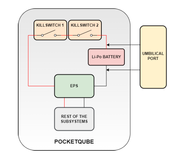
Figure 4: General Electric Scheme of the satellite with the killswitches and umbilical port
It can be observed that, even though the kill switches are pressed, the satellite still has a direct connection to the umbilical port, allowing communication with the satellite as well as the ability to charge the battery through the umbilical port.
Once the satellite is placed in the deployer rail and the kill switches are engaged, the battery will remain in standby mode, meaning it won’t charge or discharge actively. However, this will lead to a slow, passive discharge of the battery over time.
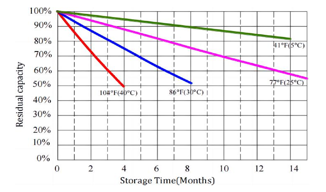
Figure 5: Capacity Discharged vs Storage Time and Temperature
According to the manufacturer’s data (figure 5), the rate of discharge depends on the temperature and how long the battery remains without the ability to charge. While these values are theoretical, in practice, the actual discharge rate can vary due to several factors. Nonetheless, these estimates provide a general idea of how long the satellite’s battery can remain without charging.
