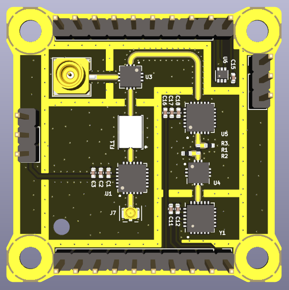


The objective of this document is to detail the procedures, results and conclusions to properly test at subsystem level the RFI-5G front-end top board. Several parts will be tested:
The as run versions of this document will have the title as "RFI-5G FE-Top SSV as run dd/mm/yyyy".
The purpose of this test is to validate that the HMC342 LNA amplifier provides the expected +19 dB of gain for input signals between 24 to 25 GHz, and that the band-pass filter does not introduce more than the expected -4 dB of losses.
Since the probing used is not the frequency range used, this is only a qualitative test to check if the LNA is providing gain and validate that the consumption is nominal.
This test does not verify any requirement, and is only to check that the board part works as expected.
The required components for this test are the following:
| RFI-5G front-end top board |
|
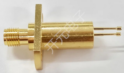
| C.FL to SMA-2.92mm adapter |
|
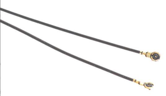
| C.FL cable |
|
| RF probe |
|
| SMA 50 Ohm RF load |
|
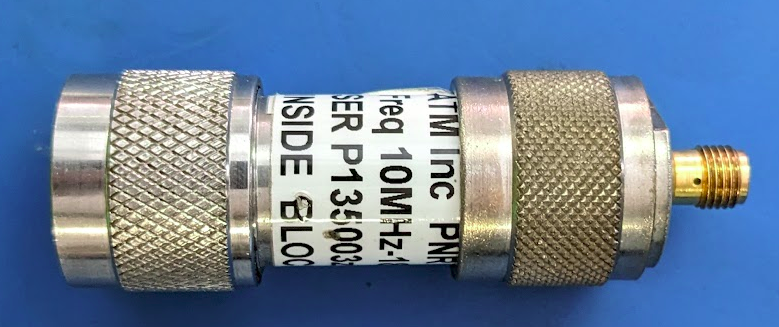
| DC Block N to SMA adapter |
|
| Power supply |
|
| Signal Generator capable of at least 25 GHz |
|
| Spectrum Analyzer capable of at least 25 GHz |
|
| 2x Jumper cables |
|
| 2x Banana cables |
|
| 2x Crocodrile clips |
|
| 2x SMA 2.92 mm cables |
|
| SMA to SMP cable |
|
The steps to prepare the setup are the following:
The diagram below represents the initial setup:
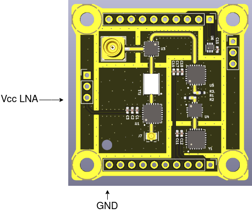
The test will be considered successful if the LNA shows to provide gain (~19 dB) and the power consumption matches the expected one (~43 mA at 3.3 V). There is though some margin accepted, since the RF probe and cables are not rated for the frequency range used.
|
Step ID |
Description |
Pass/Fail Criteria |
Actual |
Passed [Y/N] |
| RFI-5G-TOP-LNA-000 |
Make sure that the power supply and signal generator outputs are off. | Passes if power supply and signal generator outputs are off. |
ok |
y |
| RFI-5G-TOP-LNA-010 |
Prepare the setup as stated in 2.3. |
Passes if setup prepared. |
setup done |
y |
| RFI-5G-TOP-LNA-020 |
Set the power supply to 3 V and limit the current to 60 mA. |
Passes if power supply set. |
power supply set |
y |
| RFI-5G-TOP-LNA-030 |
Set the signal generator to: f = 24.5 GHz Pout = -70 dBm |
Passes if signal generator set. |
signal generator set |
y |
| RFI-5G-TOP-LNA-040 |
Set the spectrum analyzer to: f = 24.5 GHz Span = 10 MHz RBW = 10 kHz VBW = 1 kHz Trace = Max Hold |
Passes if spectrum analyzer set. |
spectrum analyzer set |
y |
| RFI-5G-TOP-LNA-050 |
Switch on the signal generator output. |
Passes if signal generator output is on. |
signal generator on |
y |
| RFI-5G-TOP-LNA-060 |
Switch on the power supply. If the power supply is limiting switch it off immediately. |
Passes if power supply is on and not current limiting. |
power supply on |
y |
| RFI-5G-TOP-LNA-070 |
Note the voltage and current. If the current consumption is abnormal switch it off immediately. |
Passes if voltage and current are within specification (some margin is allowed but has to be explained why). |
Voltage: 2.99 V Current: 40 mA |
y |
| RFI-5G-TOP-LNA-080 |
With the RF probe, probe the input of the LNA by carefully touching with the signal pogo-pin the RF input pin of the LNA. |
Passes if a signal is shown in the spectrum analyzer. |
signal appears if signal generator power is -50 dBm due to probe |
y |
| RFI-5G-TOP-LNA-090 | Set the trace mode in the spectrum analyzer to VIEW to freeze the image. |
Passes if trace mode is VIEW. |
trace mode VIEW |
y |
|
RFI-5G-TOP-LNA-100 |
Add a second trace in the spectrum analyzer with the same configuration as the first one. |
Passes if spectrum analyzer set. |
spectrum analyzer set |
y |
| RFI-5G-TOP-LNA-110 | With the RF probe, probe the output of the LNA by carefully touching with the signal pogo-pin the RF output pin of the LNA. |
Passes if a signal is shown in the spectrum analyzer. | signal shows in spectrum analyzer |
y |
| RFI-5G-TOP-LNA-120 | Set the trace mode in the spectrum analyzer to VIEW to freeze the image. |
Passes if trace mode is VIEW. |
trace mode VIEW |
y |
| RFI-5G-TOP-LNA-130 |
Add one marker to the peak of trace 1, and another marker that measures the delta in the peak of trace 2. Note the gain and frequency delta values. |
Passes if the gain is within specification (some margin is allowed but has to be explained why). |
Gain: 15.8 dB Frequency: 0 Hz |
y |
| RFI-5G-TOP-LNA-140 |
Capture the screen of the spectrum analyzer and save it into a USB drive. |
Passes if .wmf is saved into a USB drive. |
File name: LNA_001.wmf |
y |
| RFI-5G-TOP-LNA-150 |
Add a third trace in the spectrum analyzer with the same configuration as the first one. |
Passes if spectrum analyzer set. |
third trace added |
y |
| RFI-5G-TOP-LNA-160 | With the RF probe, probe the output of the band-pass filter by carefully touching with the signal pogo-pin the RF output pin of the filter. | Passes if the gain is within specification (some margin is allowed but has to be explained why). |
signal shows in spectrum analyzer |
y |
| RFI-5G-TOP-LNA-170 | Set the trace mode in the spectrum analyzer to VIEW to freeze the image. |
Passes if trace mode is VIEW. |
trace mode VIEW |
y |
| RFI-5G-TOP-LNA-180 |
Add a third marker in trace 3. Note the power and frequency delta values with marker 1. |
Passes if the gain is within specification (some margin is allowed but has to be explained why). |
Gain: 11.15 dB Frequency: 0 Hz |
y |
| RFI-5G-TOP-LNA-190 |
Capture the screen of the spectrum analyzer and save it into a USB drive. |
Passes if .wmf is saved into a USB drive. |
File name: LNA_002.wmf |
y |
| RFI-5G-TOP-LNA-200 |
Switch off the power supply and the signal generator. |
Passes if power supply and signal generator are off. |
power supply and signal generator off |
y |
| RFI-5G-TOP-LNA-210 |
If all steps are passed, proceed with next test. |
Passes if all steps passed. |
Discussion in results |
y |
LNA:
Perceived LNA gain is of ~16 dB. Compared to the expected 19.2 dB of gain, the performance is considered valid, since the measuring technique introduces losses that are not accounted for. Additionally, the power consumption of 40 mA seems o be nominal since the expected was 43 mA.

Band-pass filter:
The band-pass filter seems to introduce ~4 dB of losses, which was expected from the specifications.

The signal power from the signal generator has been increased to 50 dBm because of the probing method used, otherwise the signal was not strong enough to be coupled to the probe and appear in the spectrum analyzer measurement.
This test concludes that the LNA chain implementation performs as expected.
The purpose of this test is to validate that the LO chain works as intended. This means that the HMC506 VCO provides a tone at the expected 8665.5 MHz, and that the HMC342 LO amplifier provides gain (~19 dB) so that the LO input of the mixer is over 12 dBm (~14 dBm).
Since the probing used is not the frequency range used, this is only a qualitative test to check if the LO chain is providing the correct LO tone to the mixer and that the consumption is nominal.
This test does not verify any requirement, and is only to check that the board part works as expected.
The required components for this test are the following:
| RFI-5G front-end top board |
|
| C.FL to SMA-2.92mm adapter |
|
| C.FL cable |
|
| RF probe |
|
| SMA 50 Ohm RF load |
|
| DC Block N to SMA adapter |
|
| Power supply |
|
| Spectrum Analyzer capable of at least 25 GHz |
|
| 6x Jumper cables |
|
| 6x Banana cables |
|
| 6x Crocodrile clips |
|
| 2x SMA 2.92 mm cables |
|
| SMA to SMP cable |
|
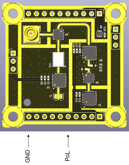
The steps to prepare the setup are the following:
The diagram below represents the initial setup:

The test will be considered successful if the LO shows a tone at 8665.5 MHz +- 5%, if the LO amplifier provides the expected gain (~19 dB) and if the level of the LO input of the mixer is over 10 dBm. Additionally, the current consumption has to be nominal.
|
Step ID |
Description |
Pass/Fail Criteria |
Actual |
Passed [Y/N] |
| RFI-5G-TOP-LO-000 |
Make sure that the power supply is off. |
Passes if power supply and signal generator outputs are off. |
power supply off |
y |
| RFI-5G-TOP-LO-010 |
Prepare the setup as stated in 3.3. |
Passes if setup prepared. |
setup prepared |
y |
| RFI-5G-TOP-LO-020 |
Set the first channel of the power supply to 3 V and limit the current to 100 mA. |
Passes if power supply set. |
ch1 set |
y |
| RFI-5G-TOP-LO-030 |
Set the second channel of the power supply to 8.7 V and limit the current to 10 mA. |
Passes if power supply set. |
ch2 set |
y |
| RFI-5G-TOP-LO-040 | Set the third channel of the power supply to 3 V and limit the current to 60 mA. |
Passes if power supply set. |
ch3 set |
y |
| RFI-5G-TOP-LO-050 |
Set the spectrum analyzer to: f = 8665.5 MHz Span = 100 MHz RBW = 100 kHz VBW = 3 kHz Trace = Clear/Write |
Passes if spectrum analyzer set. |
spectrum analyzer set |
y |
| RFI-5G-TOP-LO-060 |
Switch on the first channel of the power supply. If the power supply is limiting switch it off immediately. |
Passes if power supply is on and not current limiting. |
ch1 on |
y |
| RFI-5G-TOP-LO-070 |
Switch on the first channel of the power supply. If the power supply is limiting switch it off immediately. |
Passes if power supply is on and not current limiting. |
ch2 on |
y |
| RFI-5G-TOP-LO-080 |
Note the voltage and current. If the current consumption is abnormal switch it off immediately. |
Passes if voltage and current are within specification (some margin is allowed but has to be explained why) |
CH1 Voltage: 3 V Current: 81 mA CH2 Voltage: 8.7 V Current: 0 mA |
y |
| RFI-5G-TOP-LO-080 |
With the RF probe, probe the output of the VCO by carefully touching with the signal pogo-pin the RF output pin of the LNA. |
Passes if a signal is shown in the spectrum analyzer. |
Signal present in spectrum analyzer |
y |
| RFI-5G-TOP-LO-090 | Adjust the Vtune1 voltage until the LO frequency is centered to the desired 8665.5 MHz. |
Passes if LO frequency is ~8665.5 MHz. |
CH2 Voltage: 8.17 V frequency: 8665.5 MHz |
y |
| RFI-5G-TOP-LO-100 | Set the trace mode in the spectrum analyzer to VIEW to freeze the image. |
Passes if trace mode is VIEW. |
trace mode VIEW |
y |
| RFI-5G-TOP-LO-110 | Capture the screen of the spectrum analyzer and save it into a USB drive. |
Passes if .wmf is saved into a USB drive. |
File name: VCO-001.wmf |
y |
| RFI-5G-TOP-LO-120 | Set the trace mode in the spectrum analyzer to CLEAR/WRITE to clear the spectrum. |
Passes if trace mode is CLEAR/WRITE. |
trace mode CLEAR/WRITE |
y |
|
RFI-5G-TOP-LO-130 |
Set the spectrum analyzer to: f = 17331 MHz Span = 200 MHz RBW = 100 kHz VBW = 3 kHz Reference level = 10 dBm Trace = Max Hold |
Passes if spectrum analyzer set. |
spectrum analyzer set |
y |
| RFI-5G-TOP-LO-140 | With the RF probe, probe the output of the frequency multiplier by carefully touching with the signal pogo-pin the RF output pin of the frequency multiplier. |
Passes if a signal is shown in the spectrum analyzer. | signal shows in spectrum analyzer |
y |
| RFI-5G-TOP-LO-150 | Set the trace mode in the spectrum analyzer to VIEW to freeze the image. |
Passes if trace mode is VIEW. |
trace mode VIEW |
y |
| RFI-5G-TOP-LO-160 |
Add one marker at the peak. Note the power and frequency values. | Passes if power and frequency are within specification. |
Power: -25.92 dBm Frequency: 17335.8 MHz |
y |
| RFI-5G-TOP-LO-170 |
Add a second trace in the spectrum analyzer with the same configuration as the first one. | Passes if spectrum analyzer set. | spectrum analyzer set |
y |
| RFI-5G-TOP-LO-180 |
Switch on the third channel of the power supply. If the power supply is limiting switch it off immediately. |
Passes if power supply is on and not current limiting. |
ch3 on |
y |
| RFI-5G-TOP-LO-190 | Note the voltage and current. If the current consumption is abnormal switch it off immediately. |
Passes if voltage and current are within specification (some margin is allowed but has to be explained why) |
CH3 Voltage: 3 V Current: 44 mA |
y |
| RFI-5G-TOP-LO-200 |
With the RF probe, probe the output of the LO amplifier by carefully touching with the signal pogo-pin the RF output pin of the LO amplifier. |
Passes if a signal is shown in the spectrum analyzer. |
signal shows in spectrum analyzer |
y |
| RFI-5G-TOP-LO-210 | Set the trace mode in the spectrum analyzer to VIEW to freeze the image. |
Passes if trace mode is VIEW. |
trace mode VIEW |
y |
| RFI-5G-TOP-LO-220 | Add one marker to the peak of trace 1, and another marker that measures the delta in the peak of trace 2. Note the power and frequency delta values. |
Passes if the gain is within specification (some margin is allowed but has to be explained why). |
Power: 11.07 dB Frequency: 0.8 kHz |
y |
| RFI-5G-TOP-LO-230 | Capture the screen of the spectrum analyzer and save it into a USB drive. |
Passes if .wmf is saved into a USB drive. |
File name: DOUBLER_001.wmf |
y |
| RFI-5G-TOP-LO-240 | Switch off the power supply and the signal generator. |
Passes if power supply and signal generator are off. |
power supply off |
y |
| RFI-5G-TOP-LO-250 | If all steps are passed, proceed with next test. |
Passes if all steps passed. |
Discussion in results |
y |
VCO:
The VCO output provides a tone centered to a frequency provided by the Vtune voltage. In order to obtain the desired 8665.5 MHz of VCO frequency, the tuning voltage has been lowered from the expected 8.7 V to 8.17 V. Additionally, the frequency tuning appears to be erroneous: when the front-end is shifted or the cables are moved, the output of the VCO varies significantly.
The power consumption of the VCO is of 81 mA at 3 V, which is higher than the expected 77 mA from the specification. The reasoning of this increase in consumption might be the bad connections used with the jumper.

Frequency doubler and amplifier:
The frequency doubler doubles the VCO output tone accordingly. The losses introduced by the doubling cannot be measured accurately.
The LO amplifier provides a net gain of ~11 dB, and when considering the 50 Ohm resistor in series at its input to reduce the signal power that adds ~4dB of extra losses , the behavior of the amplifier is in pair with the LNA (is the same ic). The power consumption appears to be of a nominal 40 mA.

The list of anomalies is shown below:
The VCO behavior is validated, but its characteristics need to be measured with the interface board attached, to reduce the impedance of the jumper cables used and improve the performance.
The purpose of this test is to validate the correct functioning of the RF part of the RFI-5G front-end top, i.e., with an input signal between 24-25 GHz, the signal is down-converted to an intermediate signal with frequency between 6669-76669 MHz, with a net gain of 5 dB.
This test does not verify any requirement, and is only to check that the board part works as expected.
The required components for this test are the following:
| RFI-5G front-end top board |
|
| RFI-5G interface board with inverse connectors |
|
| C.FL to SMA-2.92mm adapter |
|
| C.FL cable |
|
| DC Block N to SMA adapter |
|
| Power supply |
|
| Signal Generator capable of at least 25 GHz |
|
| Spectrum Analyzer capable of at least 25 GHz |
|
| 2x Banana cables |
|
| SMA 2.92 mm cables |
|
| SMA to SMP cable |
|
The steps to prepare the setup are the following:
The diagram below represents the initial setup:
The test will be considered successful if the output of the RFI-5G front-end top board is a signal between 6669-7669 MHz when the antenna input is between 24-25 GHz, and the board provides a net gain of +5 dB. Additionally, the current consumption has to be nominal.
|
Step ID |
Description |
Pass/Fail Criteria |
Actual |
Passed [Y/N] |
| RFI-5G-TOP-RF-000 |
Make sure that the power supply and signal generator outputs are off. | Passes if power supply and signal generator outputs are off. |
power supply and signal generator off |
y |
| RFI-5G-TOP-RF-010 |
Prepare the setup as stated in 4.3. |
Passes if setup prepared. |
setup prepared |
y |
| RFI-5G-TOP-RF-020 |
Set the first channel of the power supply to 3.3 V and limit the current to 200 mA. |
Passes if power supply set. |
power supply set |
y |
| RFI-5G-TOP-RF-030 |
Set the spectrum analyzer to: f = 7169 MHz Span = 200 MHz RBW = 100 kHz VBW = 3 kHz Reference level = -20 dBm Trace = Clear/Write |
Passes if spectrum analyzer set. |
spectrum analyzer set |
y |
| RFI-5G-TOP-RF-040 |
Set the signal generator to: f = 24.5 GHz Pout = -80 dBm |
Passes if signal generator set. | signal generator set |
y |
| RFI-5G-TOP-RF-050 |
Switch on the first channel of the power supply. If the power supply is limiting switch it off immediately. |
Passes if power supply is on and not current limiting. |
power supply on |
y |
| RFI-5G-TOP-RF-060 | Note the voltage and current. If the current consumption is abnormal switch it off immediately. |
Passes if voltage and current are within specification (some margin is allowed but has to be explained why). |
CH1 Voltage: 3.3 V Current: 150 mA |
y |
| RFI-5G-TOP-RF-070 | Enable the output of the signal generator. | Passes if signal generator output is enabled. | signal generator enabled |
y |
| RFI-5G-TOP-RF-080 | Note the voltage and current. If the current consumption is abnormal switch it off immediately. |
Passes if voltage and current are same as in RFI-5G-TOP-RF-060. |
CH1 Voltage: 3.3 V Current: 150 mA |
n |
| RFI-5G-TOP-RF-090 | Add one marker at the peak. Note the frequency and power of the intermediate signal. Additionally compute the net gain and the frequency shift. | Passes if the net gain is +5 dB and the frequency shift of 17331 MHz. |
frequency = Power = frequency shift = Gain = |
n |
| RFI-5G-TOP-RF-100 | Set the trace mode in the spectrum analyzer to VIEW to freeze the image. |
Passes if trace mode is VIEW. |
||
| RFI-5G-TOP-RF-110 | Capture the screen of the spectrum analyzer and save it into a USB drive. |
Passes if .wmf is saved into a USB drive. |
File name: |
|
| RFI-5G-TOP-RF-120 | Set the trace mode in the spectrum analyzer to CLEAR/WRITE to clear the spectrum. |
Passes if trace mode is CLEAR/WRITE. | ||
| RFI-5G-TOP-RF-130 |
Switch off the output of the signal generator. |
Passes if signal generator output is off. |
||
| RFI-5G-TOP-RF-140 |
Set the spectrum analyzer to: f = 7169 MHz Span = 1200 MHz RBW = 300 kHz VBW = 30 kHz Trace = Max Hold |
Passes if spectrum analyzer set. |
||
| RFI-5G-TOP-RF-150 |
Set the signal generator to: Mode = frequency sweep f = 24.5 GHz Span = 1 GHz Step = 10 MHz P = -80 dBm |
Passes if signal generator set. |
|
|
| RFI-5G-TOP-RF-160 |
Switch on the output of the signal generator. |
Passes if signal generator output is on. |
||
| RFI-5G-TOP-RF-170 | Wait until a complete frequency sweep is done. | Passes when complete frequency sweep finishes. | ||
| RFI-5G-TOP-RF-180 | Check qualitatively the flatness of the RFI-5G front-end top board RF output. | Passes if the RF output is "flat". | ||
| RFI-5G-TOP-RF-190 | Set the trace mode in the spectrum analyzer to VIEW to freeze the image. |
Passes if trace mode is VIEW. |
|
|
| RFI-5G-TOP-RF-200 | Capture the screen of the spectrum analyzer and save it into a USB drive. |
Passes if .wmf is saved into a USB drive. |
File name: |
|
| RFI-5G-TOP-RF-210 | Switch off the power supply and the signal generator. |
Passes if power supply and signal generator are off. |
||
| RFI-5G-TOP-RF-220 | If all steps are passed, proceed with next test. |
Passes if all steps passed. |
The mixer does not seem to perform the frequency downconversion
Upon investigation
List of deviations to the Test Specification and Procedure and non-conformances witnessed during the test campaign, including a brief description, the close-out status and reference to the relevant reports.
The Conclusions shall include (where needed as annex):
The purpose of this test is to validate the correct functioning of temperature sensor in the RFI-5G front-end top board, and that the sensor library code functions correctly.
This test does not verify any requirement, and is only to check that the board part works as expected.
The required components for this test are the following:
| RFI-5G front-end top board |
|
| RFI-5G interface board with inverse connectors |
|
| RFI-5G EGSE |
|
| STM32 Nucleo-L476RG board |
|
| USB A-to-mini cable |
|
| Power supply |
|
| 2x Banana cables |
|
| 2x Jumper cables |
|
| Temperature sensor test code |
NA |
The steps to prepare the setup are the following:
The diagram below represents the initial setup:
Missing setup picture
Description of which metric is used to perform the test and when it is considered that the test passed or not. If different metrics are used, it is important to define when the test passed or not (e.g. when all the metrics are in the pass criteria, or when only one of them).
This section includes the test sequence necesary to do the test. The test sequence must include all the steps, from the set-up up to the conclusion of the test.
Description of the Test results with supporting data.
List of deviations to the Test Specification and Procedure and non-conformances witnessed during the test campaign, including a brief description, the close-out status and reference to the relevant reports.
The Conclusions shall include (where needed as annex):

