
This are the necessary materials to install helicoils:
The initial step involves taking tool A and using it to create a base with the utensil, enabling the subsequent screwing of the nails.

Subsequently, we'll affix a helicoil onto tool B, ensuring it is securely attached to the tool's end.

The following step involves inserting the helicoil into the hole created in the initial step, securing it by screwing, as illustrated in the preceding image.

We will tighten the nail until it no longer sticks out from the hole.

Once the helicoil is no longer visible, we will retrieve tool B by rotating it in the opposite direction.

Finally, we will utilize tool C to break the metallic part at the end of the helicoil, allowing us to insert the nails.


Now, we can securely screw nails into places where it was not possible before!
# COMMS Antenna Refurbishment ## Materials #### PocketQube body: Should already contain all the components of the spacecraft, inluding all the subsystem boards and the battery. [](https://wiki.nanosatlab.space/uploads/images/gallery/2023-10/photo1698490172-1.jpeg) #### Lateral board with antenna: The antenna must be already soldered and must have space to add a resistor in the opposite side (as seen in the image). [](https://wiki.nanosatlab.space/uploads/images/gallery/2023-10/photo1698490172.jpeg) #### Resistor: 7.5 Ohm resistor (color code(5 bands): Violet, Green, Black, Silver, Brown) [](https://wiki.nanosatlab.space/uploads/images/gallery/2023-10/photo1698490946.jpeg) #### Dyneema: Dyneema bought from Decathlon (UHMPE 0.35mm diameter, 26 kg) [](https://wiki.nanosatlab.space/uploads/images/gallery/2023-10/photo1698491333.jpeg) ## Procedure #### 1. Dyneema Cut a 40cm piece of dyneema (it is recommended to use heat to cut as it leaves the ends melted and will be useful to tie knots). 40cm will be more than enough and in the end we will have leftover dyneema that we'll have to cut. [](https://wiki.nanosatlab.space/uploads/images/gallery/2023-10/photo1698491663.jpeg) #### 2. Solder resistor We solder the 7.5 ohms resistor in the opposite side of the antenna [](https://wiki.nanosatlab.space/uploads/images/gallery/2023-10/LYephoto1698490946-1.jpeg) The result should look like the previous image. #### 3. Antenna Knot 1- Bend one of the 2 ends of the cable so that one side is ~5 cm and the other is ~35 cm [](https://wiki.nanosatlab.space/uploads/images/gallery/2023-10/photo1698498859.jpeg) 2- Pass the cable through the hole previously made in the antenna in such a way that it looks like the following image [](https://wiki.nanosatlab.space/uploads/images/gallery/2023-10/photo1698498859-1.jpeg) 3- Pass the 2 ends of the cables inside the hole as you can see in the following image [](https://wiki.nanosatlab.space/uploads/images/gallery/2023-10/photo16984988592-2.jpeg) Here is another example of how it should be done using longer cables: [](https://wiki.nanosatlab.space/uploads/images/gallery/2023-10/photo1698500010.jpeg) 4- Pull the two ends of the cable until we have a knot left [](https://wiki.nanosatlab.space/uploads/images/gallery/2023-10/photo1698498859-2.jpeg) 5- You can trim the end of the rope on the shorter side (although not too much to avoid undoing the knot). 6- Once the first knot is made, we will pull the longest side of the dyneema and wrap it around the satellite until we reach the resistance. In this way the antenna will be "bent" and we can use the resistance as a thermal knife. It is very important to make the antenna bent towards the opposite side of the resistance (in such a way that we have to make a complete turn around the satellite with the rope) to prevent the antenna from taking up more space than allowed. Here are some images showing how it whould be done, also as a remark the cable used in the images is longer than it should be to help to see how to do the procedure: [](https://wiki.nanosatlab.space/uploads/images/gallery/2023-10/photo1698500459.jpeg) [](https://wiki.nanosatlab.space/uploads/images/gallery/2023-10/photo1698500459-1.jpeg) [](https://wiki.nanosatlab.space/uploads/images/gallery/2023-10/photo1698500459-2.jpeg) #### 4. Resistor Knot The crossbow knot was selected as it was robust and melted the dyneema in 14 seconds using 3.3V and 450mA. That does not mean that it is the most robust knot that exists. In fact, there are other more robust knots but the disadvantage is that they require more time to melt (that is, more energy). 1- Pull the thread in such a way that the antenna is tensioned and hooked to the sides of the satellite. [](https://wiki.nanosatlab.space/uploads/images/gallery/2023-10/photo1698501614.jpeg) 2- Pass the dyneema under the resistance so that the thread comes out towards us. The outgoing cable must pass to the right of the incoming cable (as seen in the image). [](https://wiki.nanosatlab.space/uploads/images/gallery/2023-10/photo1698501614-1.jpeg) 3- Tension the cable to be sure that the antenna is hooked to the sides. [](https://wiki.nanosatlab.space/uploads/images/gallery/2023-10/photo1698501614-2.jpeg) 4- Wrap the free end around the standing part of the rope (the part that leads to the rest of the string or object) and then bring it back down through the loop, but this time from the top. [](https://wiki.nanosatlab.space/uploads/images/gallery/2023-10/photo1698501614-3.jpeg) 5- Tighten the knot by pulling on the free end. [](https://wiki.nanosatlab.space/uploads/images/gallery/2023-10/photo1698501614-4.jpeg) Here are some images of another tutorial for this knot: [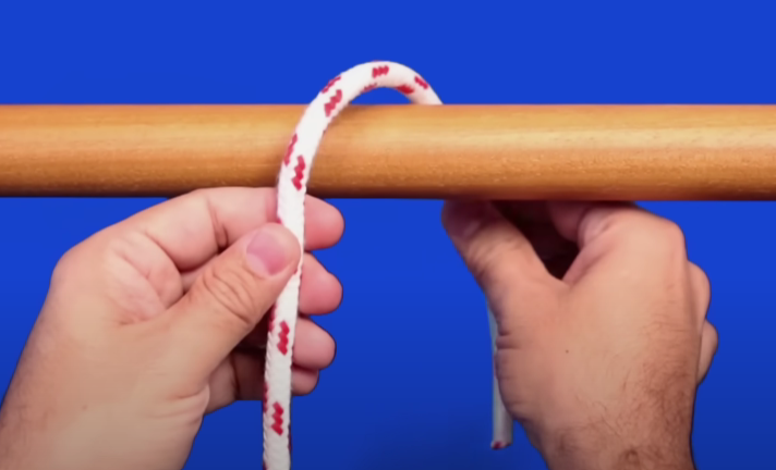](https://wiki.nanosatlab.space/uploads/images/gallery/2023-10/captura-de-pantalla-2023-10-28-161727.png) [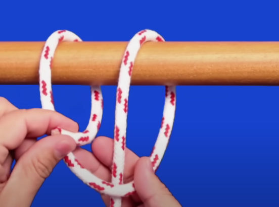](https://wiki.nanosatlab.space/uploads/images/gallery/2023-10/captura-de-pantalla-2023-10-28-161809.png) [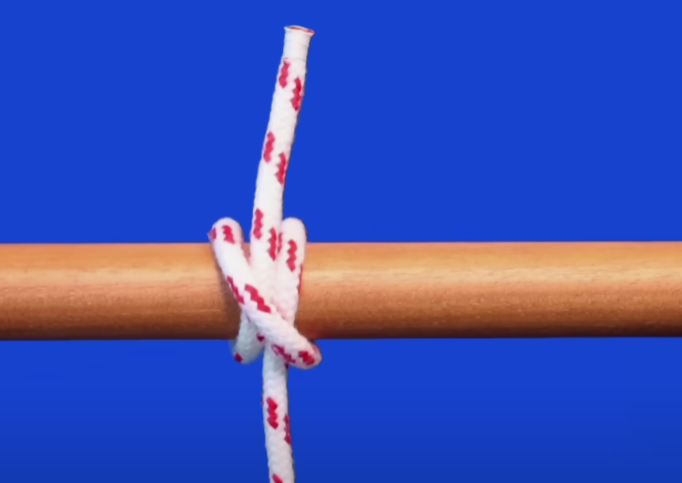](https://wiki.nanosatlab.space/uploads/images/gallery/2023-10/captura-de-pantalla-2023-10-28-161830.png) Once completed the dyneema should be tight and the end of the cables can be reduced if necessary. For extra redundancy, we recommend adding another knot on top of this, here are some images showing how to do so: [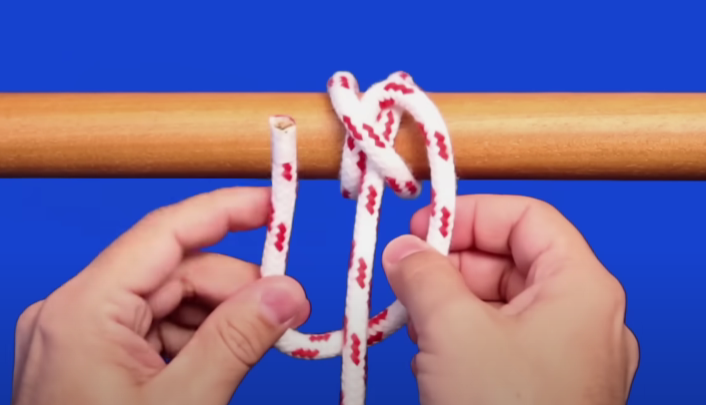](https://wiki.nanosatlab.space/uploads/images/gallery/2023-10/captura-de-pantalla-2023-10-28-162914.png) [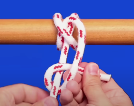](https://wiki.nanosatlab.space/uploads/images/gallery/2023-10/captura-de-pantalla-2023-10-28-162943.png) [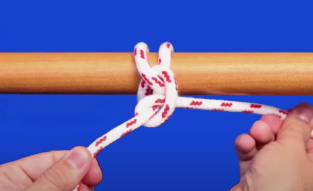](https://wiki.nanosatlab.space/uploads/images/gallery/2023-10/captura-de-pantalla-2023-10-28-163006.png) The resulting knot should look like this on the PocketQube (again, the double cable is for visualization,only one cable is necessary): [](https://wiki.nanosatlab.space/uploads/images/gallery/2023-10/photo1698503604.jpeg) Doing step 1 of the "Antenna Knot" (3) folding in half (instead of just leaving 5cm) results in greater robustness of our knot but increases the melting time of the dyneema to 31 seconds using 3.3V and 450mA. # Assembly ## INTRODUCTION This document reports the assembly and integration specifications, and includes the step-by-step procedures for the PocketQube "PAYLOAD K-BAND, L\_BAND, VGA". ## REQUIREMENTS TO BE VERIFIED| **Req. Id** | **Requirement title** | **Requirement text** | **Pass/fail criterion** | **Proc. step(s)** | **Pass** |
| SYS-PHY-01 | PQ ±X axis dimensions | 1P, 2P or 3P PocketQubes width (X direction dimension) shall be 50.0 ± 0.1 mm, with sliding plate 58.0 ± 0.1 mm wide in the same direction. | The PQ width, in the X direction, is 50.0 ± 0.1 mm, with sliding plate 58.0 ± 0.1 mm wide in the same direction. | ||
| SYS-PHY-02 | PQ ±Y axis dimensions | 1P, 2P or 3P PocketQubes height (Y direction dimension) shall be 51.6 ± 0.1 mm. This comprises 50.0 mm plus 1.6 m+m thickness of the sliding plate. | The PQ height , in the Y direction, is 51.6 ± 0.1 mm. This comprises 50.0 mm plus 1.6 m+m thickness of the sliding plate. | ||
| SYS-PHY-03 | PQ ±Z axis dimensions | 1P PocketQube length (Z direction dimension) shall be 50.0 ± 0.1 mm, with sliding plate 64.0 ± 0.1 mm long in the same direction. | The PQ length , in the Z direction, is 50.0 ± 0.1 mm, with sliding plate 64.0 ± 0.1 mm long in the same direction. | ||
| SYS-PHY-06 | PQ components and parts location ±X , +Y & ±Z axis | Components and parts may be installed on the +X, -X, +Y, +Z, -Z surfaces of the baseline PocketQube configuration, provided that they do not protrude more than 7 mm from the main body baseline envelope, and are separated more than 3.4 mm from the +Y surface of the sliding plate. | The components and parts located in the ±X , +Y & ± Z surfaces proture less than 7mm from the main body baseline envelope and are separated more than 3.4 mm from the +Y surface of the sliding plate. | ||
| SYS-PHY-07 | PQ components and parts location -Y axis | Components and parts may be installed on the -Y surface of the baseline PocketQube configuration, provided that they do not protrude more than 7 mm from the baseline envelope, and are separated more than 3 mm from the +X, -X, +Z, -Z edges of the sliding plate. | The components and parts located in the -Y surfaces proture less than 7 mm from the baseline envelope and separated more than 3 mm from the ±X & ±Z edges of the sliding plate. | ||
| SYS-PHY-08 | PQ mass | The mass of a 1P PocketQube shall not exceed 250 g. | The PQ weighs less than 250 g. | ||
| ELE-REQ-01 | Vertical PIN electric check | Each one of the pins is vertically connected. | When measuring with the multimeter the top and bottom pins (vertically alligned) a short circuit is detected. | ||
| ELE-REQ-02 | Ground connection | All the ground pins are connected to ground. | When measuring with the multimeter the ground pins (vertically alligned) a short circuit is detected. |
| **Id** | **Item** | **Qty** | **Remarks** |
| **GNDSE-01** | Screwdriver Wera 118040 TX5 (HOP 1.3) | 1 | |
| **GNDSE-02** | Screwdriver Wera 118050 TX10B0 (TX10) | 1 | |
| **GNDSE-03** | Screwdriver Wera 118090 SW 1,5 (SW 1.5) | 1 | For the M2x20 screws of the battery compartment. |
| **GNDSE-04** | Screwdriver A.402 FACOM 0.5-2.5 Nm | 1 | [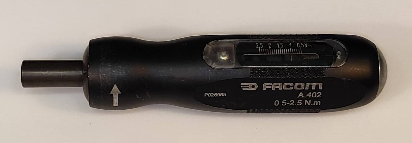](https://wiki.nanosatlab.space/uploads/images/gallery/2024-05/screwdriver-torque.jpeg) |
| **GNDSE-05** | UV light | 1 | [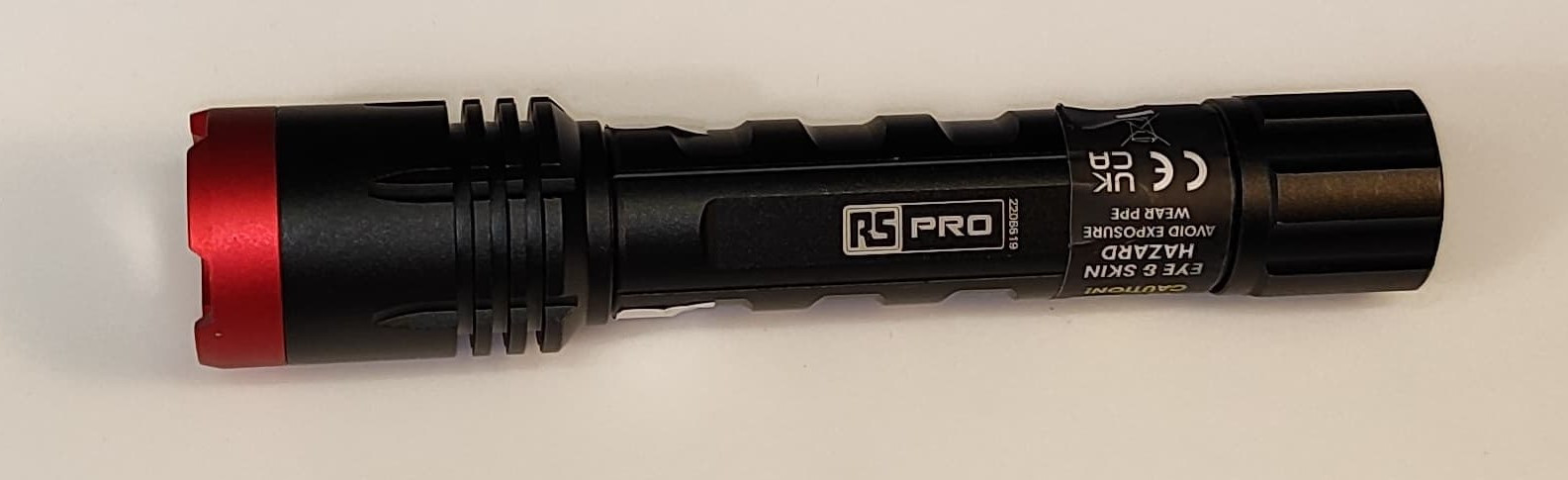](https://wiki.nanosatlab.space/uploads/images/gallery/2024-05/uv-light.jpeg) |
| GNDSE-06 | Multimeter | 1 | [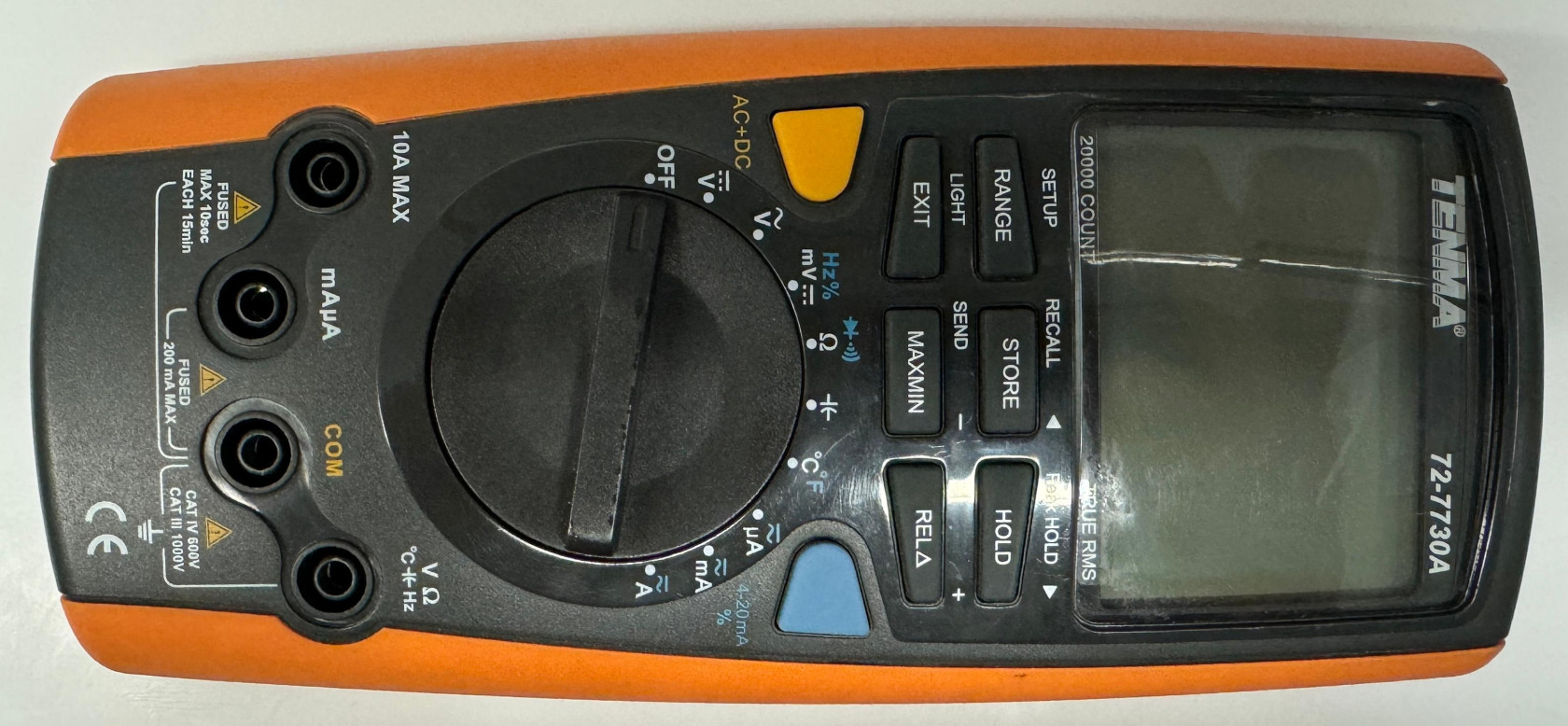](https://wiki.nanosatlab.space/uploads/images/gallery/2024-05/whatsapp-image-2024-05-01-at-17-55-32.jpeg) |
| GNDSE-07 | Vernier caliper | 1 | [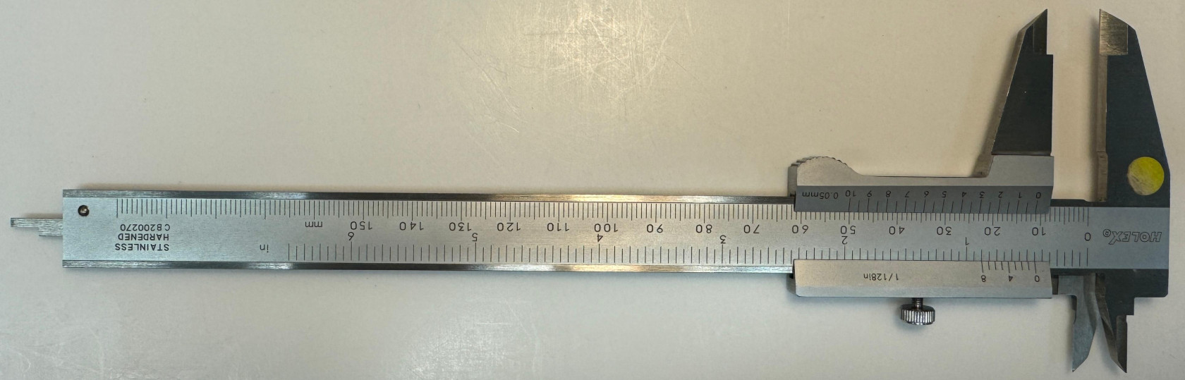](https://wiki.nanosatlab.space/uploads/images/gallery/2024-05/whatsapp-image-2024-05-01-at-17-57-47.jpeg) |
| GNDSE-08 | Scale | 1 | [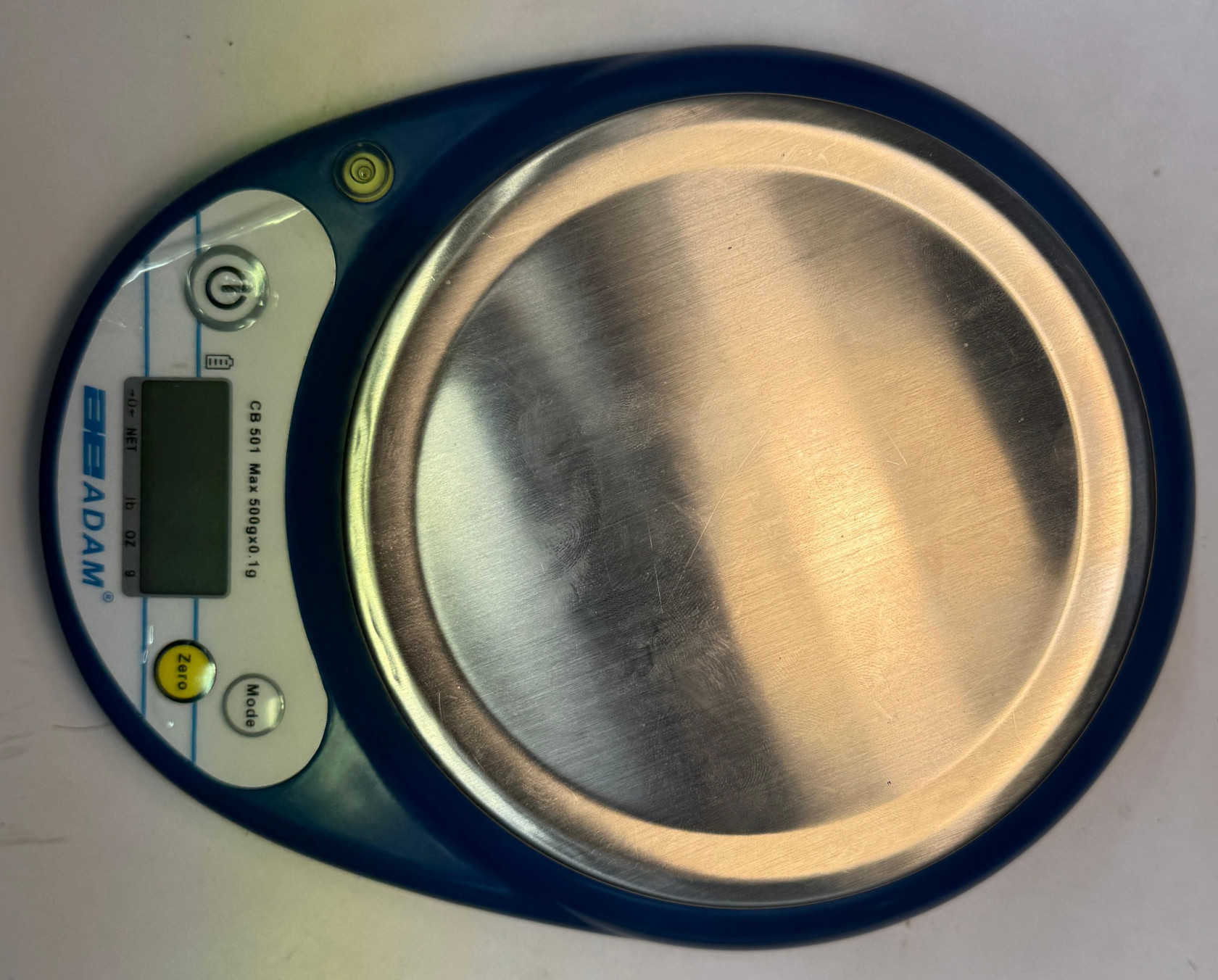](https://wiki.nanosatlab.space/uploads/images/gallery/2024-05/whatsapp-image-2024-05-01-at-18-00-19.jpeg) |
| GNDSE-09 | Kapton tape | 1 | [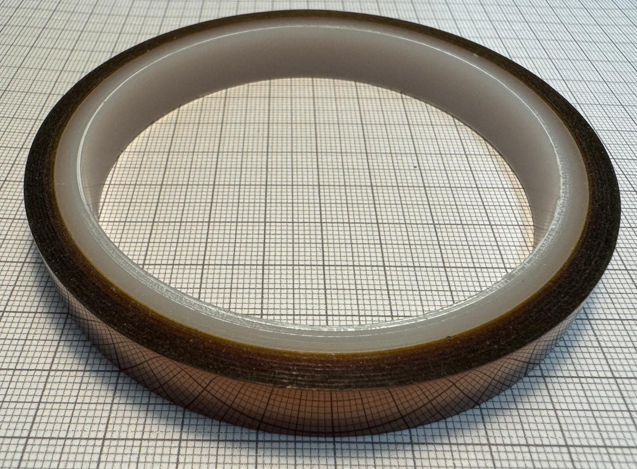](https://wiki.nanosatlab.space/uploads/images/gallery/2024-05/whatsapp-image-2024-05-06-at-11-27-17-2.jpeg) |
| GNDSE-10 | Aluminum tape | 1 | [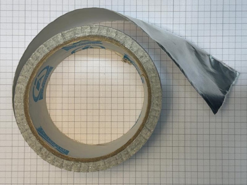](https://wiki.nanosatlab.space/uploads/images/gallery/2024-05/whatsapp-image-2024-05-06-at-11-27-17.jpeg) |
| **ID** | **Item** | **Qty** | **Photo ID** | **Remarks** |
| **SCREW-01** | **M2x6 ISO 14580** | **4** | **001627** | **Photo + Info** |
| **SCREW-02** | **M2x20 ISO 14580** | **2** | **000823** | **Photo + Info** |
| **SCREW-03** | **M2x5 ISO 14850** | **20** | **001150** | **Photo + Info** |
| **SCREW-04a** | **M3x30 ISO 7380** | **4** | **001949** | **Only VGA and L-band** |
| **SCREW-04b** | **M3X35 ISO 7380** | **4** | **002142** | **K-band (but not used)** |
| **SCREW-04c** | **M3x35 ISO 7380** | **4** | **002421** | **K-band (used)** |
| **SPACER-01** | **M2x5 Nylon** | **4** | **003413** | **Photo + Info** |
| **SPACER-02** | **M3x2 Aluminium** | **4** | **003650** | **Photo + Info** |
| **SPACER-03** | **M3x4 Aluminium** | **12** | **002915** | **Photo + Info** |
| **SPACER-04a** | **M3x0.5 Aluminium** | **12** | **003859** | **Photo + Info** |
| **SPACER-04b** | **M3x{0.1-0.5} Aluminium** | **Add necessary spacers to have a 4.6 mm distance between PCBs** | ||
| **HELICOIL-01** | ||||
| **HELICOIL-02** | ||||
| **HELICOIL-03** | ||||
| **STRUCT-01** | **Render** | |||
| **STRUCT-02** | **Render** | |||
| TCHC M3X35 INOX A4 PF DIN 912 | 4 | Standoff screws / Torque \[ 0.83678 , 1.11571 \] ( recommended , max ) [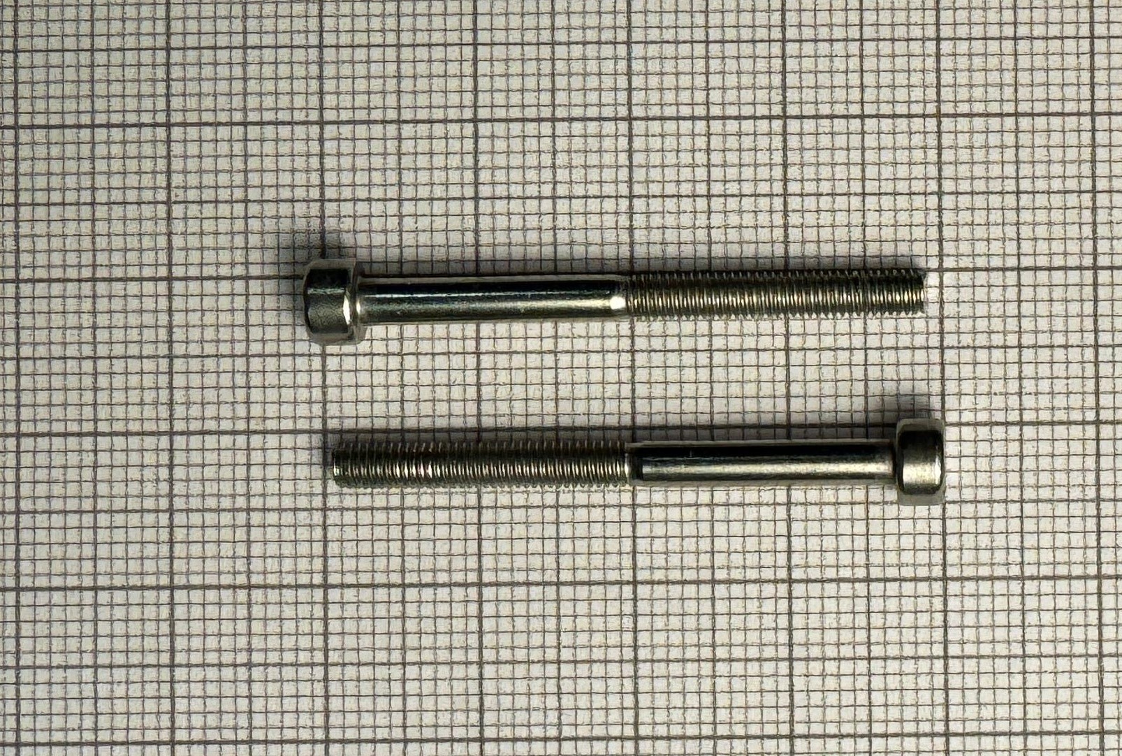](https://wiki.nanosatlab.space/uploads/images/gallery/2024-05/jT8m3x35-standoffs.jpeg) | ||
| TETE BASSE TORX M2X5 INOX A2 ISO 14580 | 20 | Lateral board screws / Torque \[ 0.229083 , 0.305444 \] ( recommended , max ) [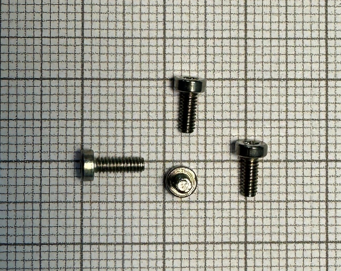](https://wiki.nanosatlab.space/uploads/images/gallery/2024-05/m2x5.jpeg) | ||
| TETE BASSE TORX M2X6 INOX A2 ISO 14580 | 4 | Bottom board screws / Torque \[ 0.229083 , 0.305444 \] ( recommended , max ) [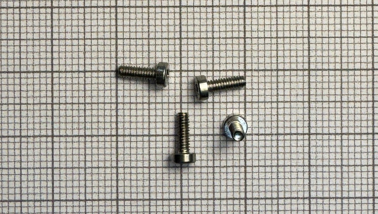](https://wiki.nanosatlab.space/uploads/images/gallery/2024-05/m2x6.jpeg) | ||
| TCHC M2X20 INOX A2 EF DIN 912 | 2 | Bottom board battery screws / Torque \[ 0.229083 , 0.305444 \] ( recommended , max ) [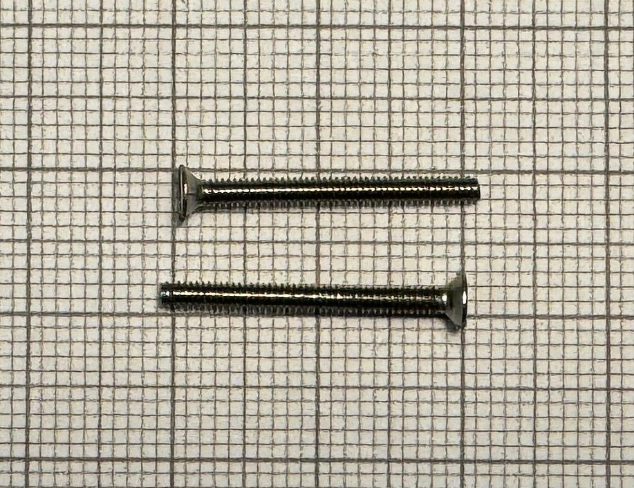](https://wiki.nanosatlab.space/uploads/images/gallery/2024-05/whatsapp-image-2024-05-02-at-16-15-24.jpeg) | ||
| HELICOIL PLUS FREE RUNNING M3X2D INOX | 4 | Helicoils for the Standoff screws on the bottom structure. [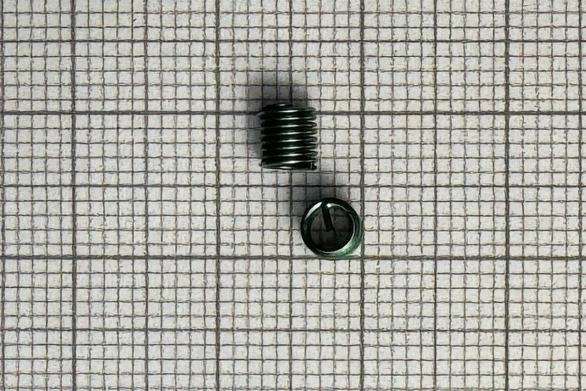](https://wiki.nanosatlab.space/uploads/images/gallery/2024-05/heli-m3x2d.jpeg) | ||
| HELICOIL PLUS FREE RUNNING M2X1,5D INOX | 16 | Helicoils for the lateral boards, 8 for the top structure and 8 for the bottom structure. [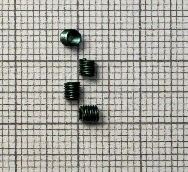](https://wiki.nanosatlab.space/uploads/images/gallery/2024-05/heli-m2x1-5d.jpeg) | ||
| HELICOIL PLUS FREE RUNNING M2X1D INOX | 10 | Helicoils for bottom board, all of them on the bottom structure. [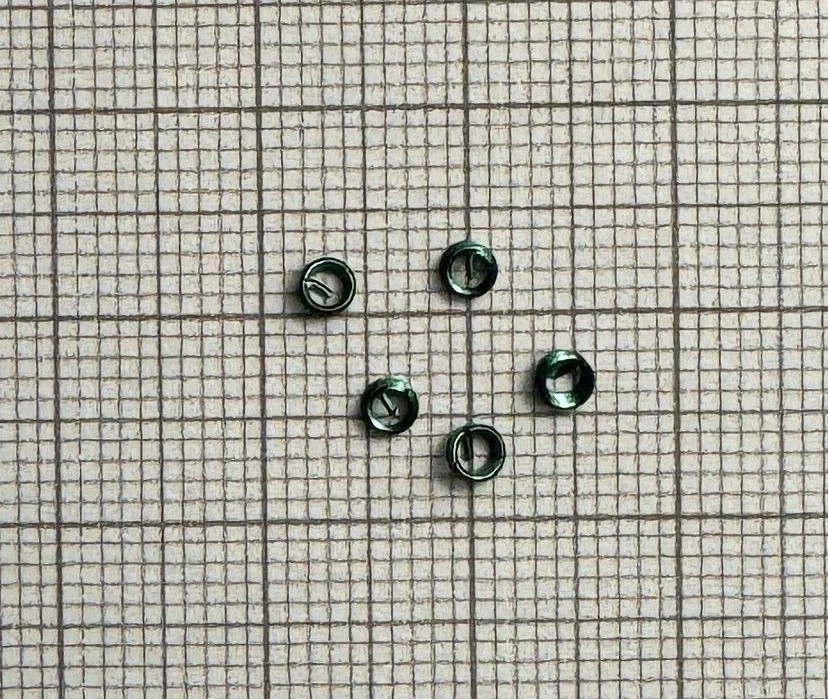](https://wiki.nanosatlab.space/uploads/images/gallery/2024-05/heli-m2x1d.jpeg) | ||
| Spacers M3X4 \[Al\] | 12 | 4mm spacers. [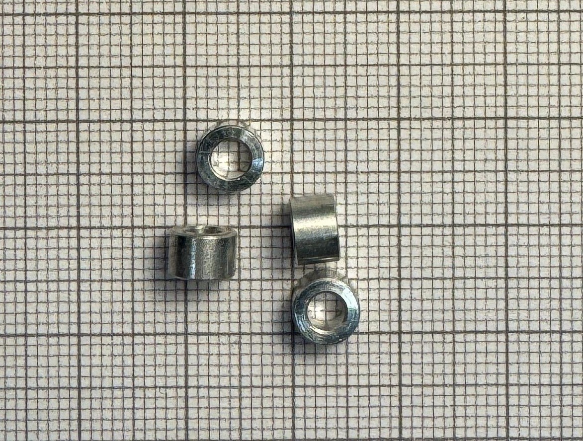](https://wiki.nanosatlab.space/uploads/images/gallery/2024-05/whatsapp-image-2024-05-02-at-15-49-23.jpeg) | ||
| Spacers 761-M0531-3-AL 2mm | 4 | 2mm spacers. [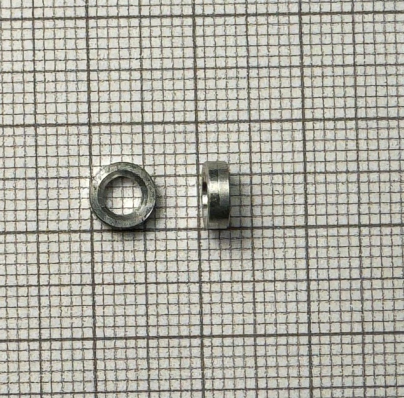](https://wiki.nanosatlab.space/uploads/images/gallery/2024-05/Vz8spacers-2mm.jpeg) | ||
| RONDELLE 3.2X6X0.5 INOX A2 DIN 433 | 12 | 0.5mm spacers. [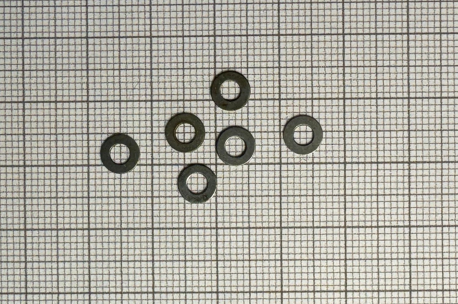](https://wiki.nanosatlab.space/uploads/images/gallery/2024-05/spacer-1mm.jpeg) | ||
| 749-906-5MM | 4 | Plastic spacers 5mm Nyl. [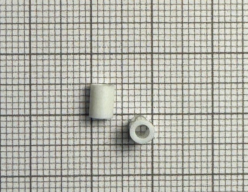](https://wiki.nanosatlab.space/uploads/images/gallery/2024-05/plastic-spacers.jpeg) | ||
| BATT-1 | Li-on Battery - 3.7 V / 1400mAh/5.18Wh - Model 103540 | 1 | Battery. [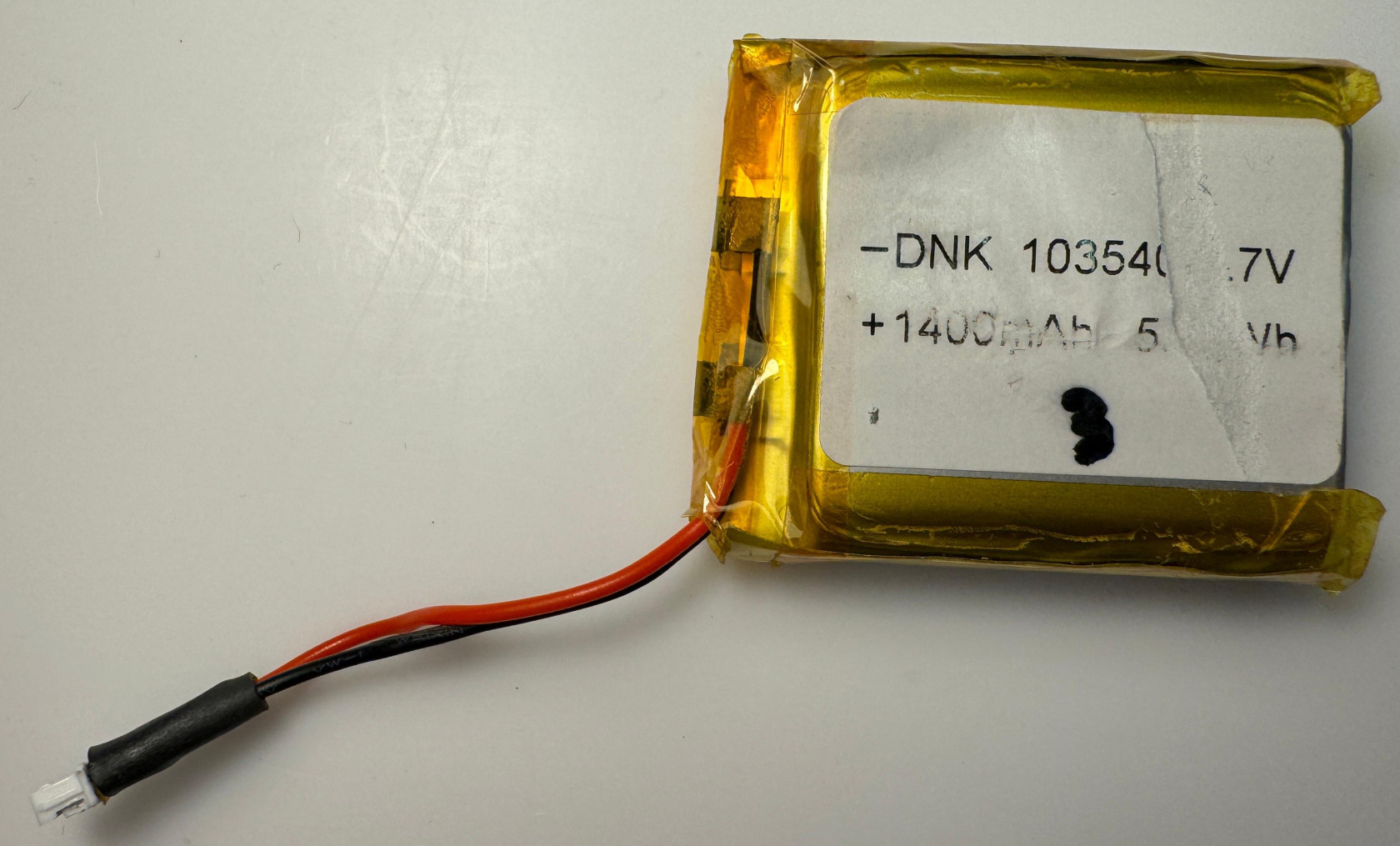](https://wiki.nanosatlab.space/uploads/images/gallery/2024-05/whatsapp-image-2024-05-01-at-16-06-02.jpeg) | |
| BOARD-1 | Fully assembled OBC-COMMS board. | 1 | Board design may be subject to small modifications. [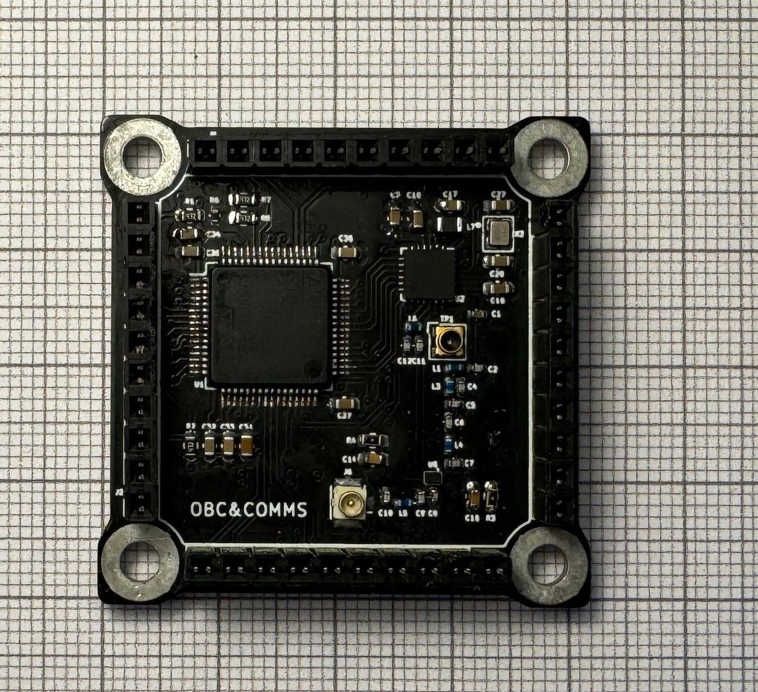](https://wiki.nanosatlab.space/uploads/images/gallery/2024-05/pcb-obccomms.jpeg) | |
| BOARD-2 | Fully assembled EPS board. | 1 | [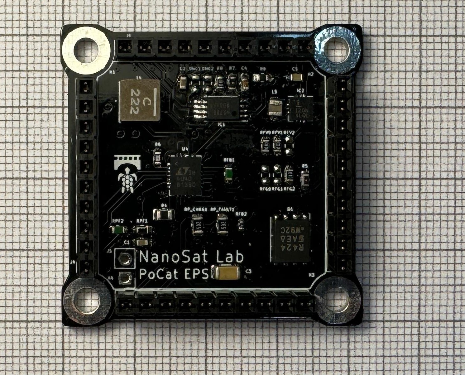](https://wiki.nanosatlab.space/uploads/images/gallery/2024-05/pcb-eps.jpeg) | |
| BOARD-3 | Fully assembled ADCS board. | 1 | [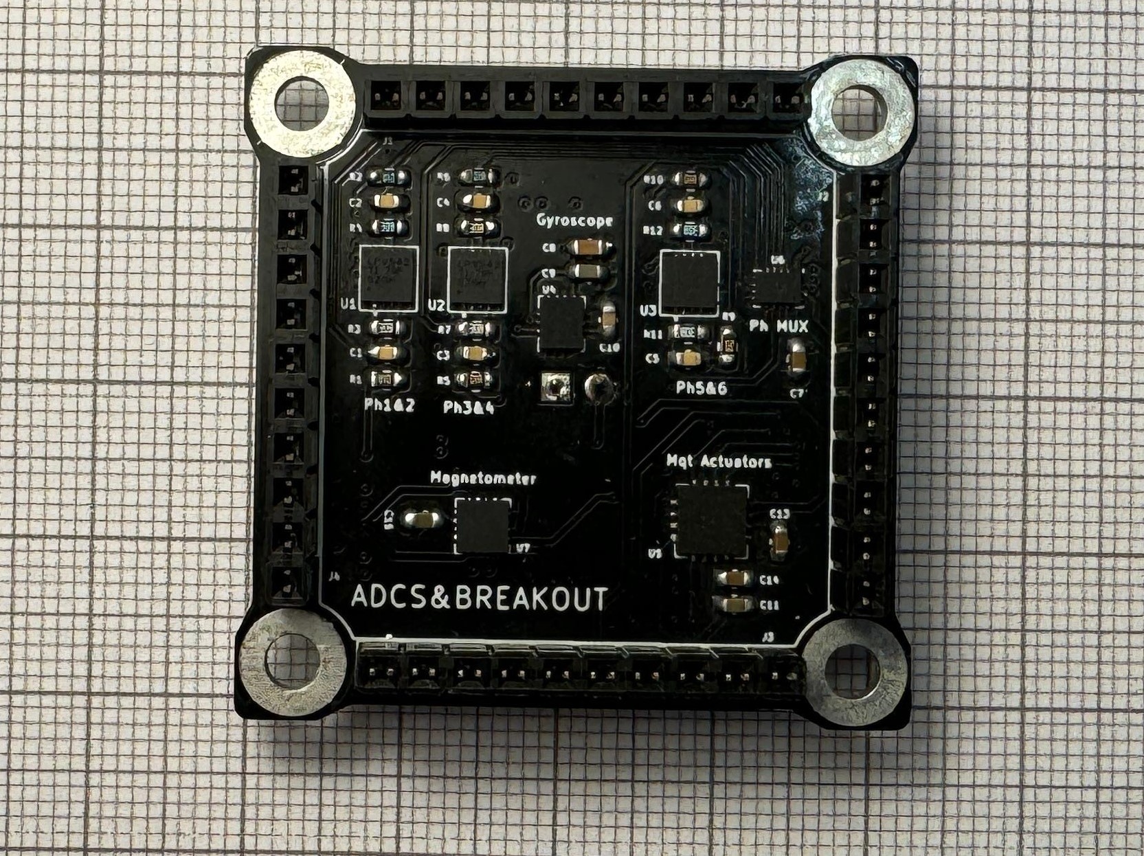](https://wiki.nanosatlab.space/uploads/images/gallery/2024-05/pcb-adcs.jpeg) | |
| BOARD-4 | Full assembled Payload 1 board. | 1 | [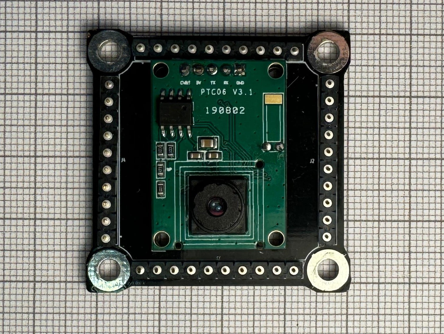](https://wiki.nanosatlab.space/uploads/images/gallery/2024-05/pcb-vga.jpeg) | |
| STRUC-1 | Top structure. | 1 | 3mm Top structure. [ 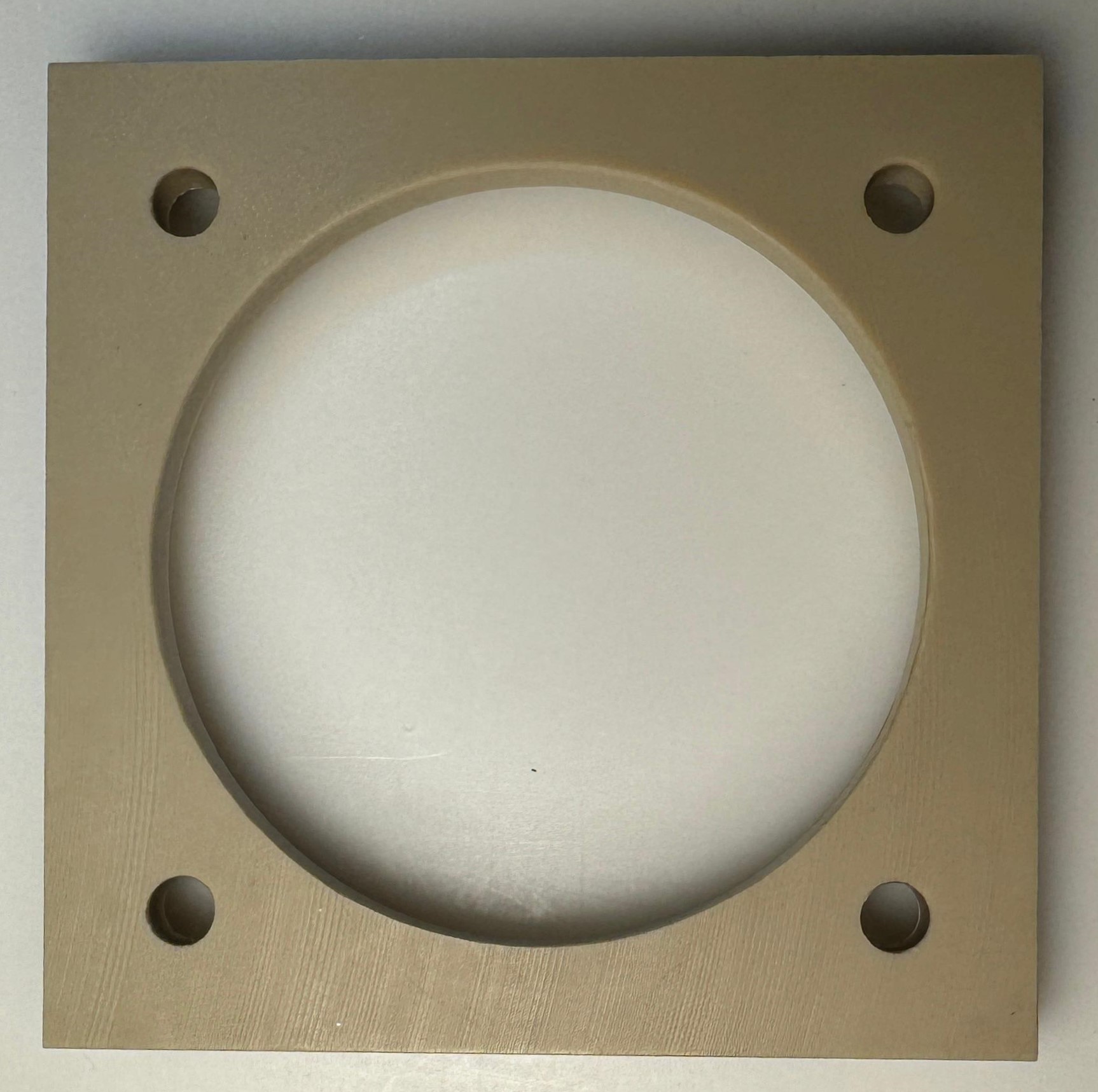](https://wiki.nanosatlab.space/uploads/images/gallery/2024-05/whatsapp-image-2024-05-01-at-16-54-21.jpeg) | |
| STRUC-2 | Bottom structure. | 1 | 3mm+10mm+3mm Bottom structure. TOP BOTTOM [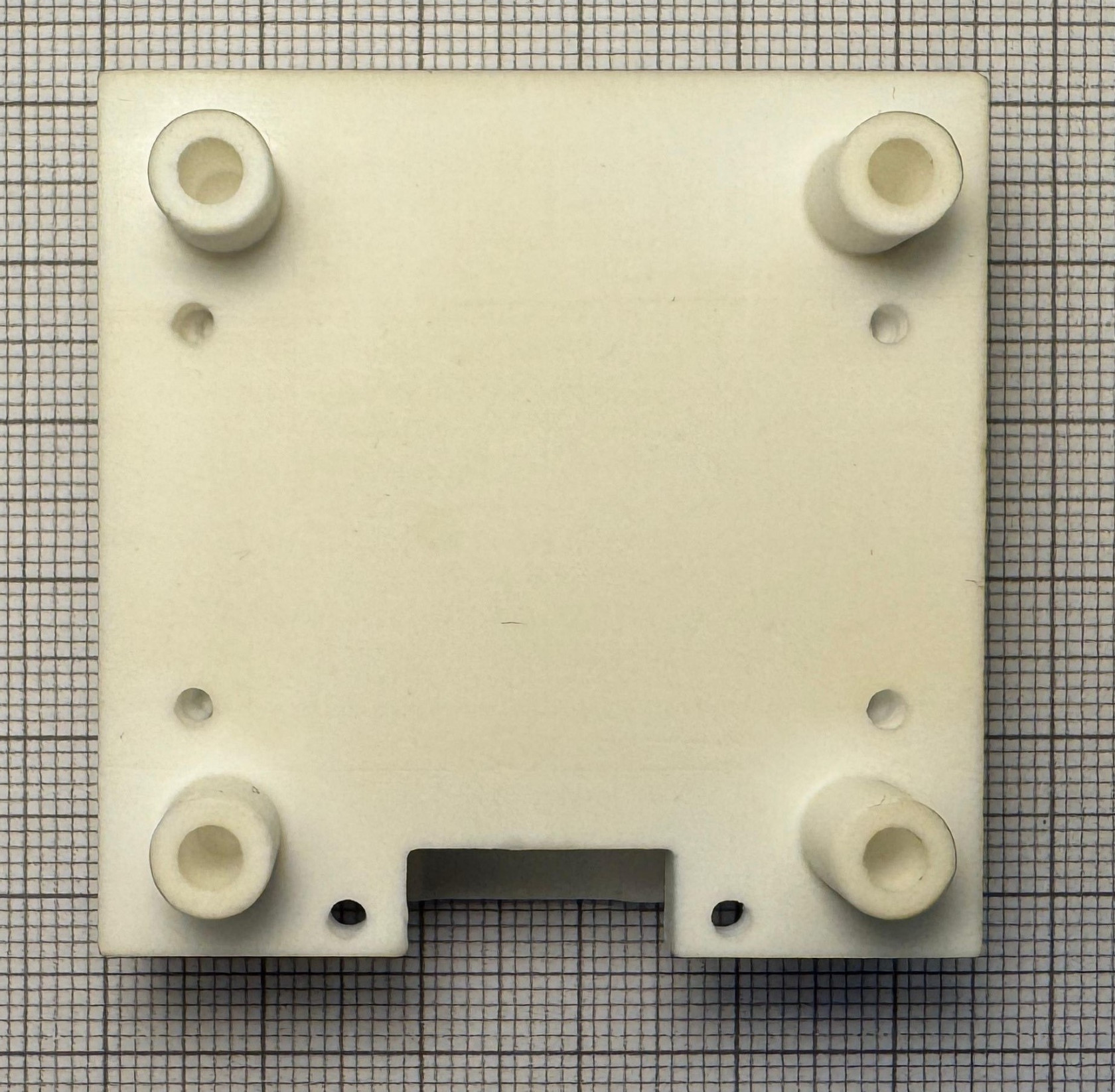](https://wiki.nanosatlab.space/uploads/images/gallery/2024-05/bot-struct-top-view.jpeg)[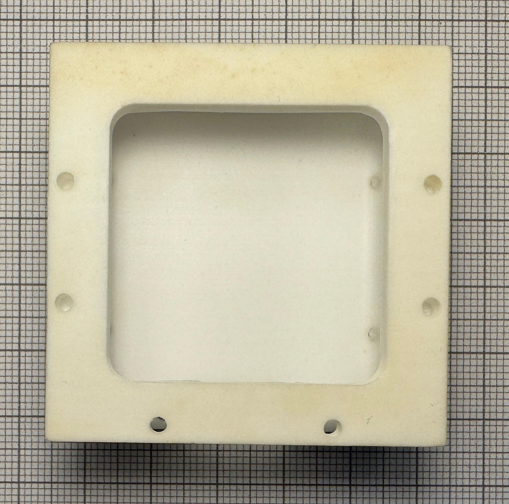](https://wiki.nanosatlab.space/uploads/images/gallery/2024-05/wvgbot-struct-bot-view.jpg) | |
| STRUC-3 | Magnetorquer PCB | 1 | +Y axis magnetorquer.
Board design may be subject to small modifications. [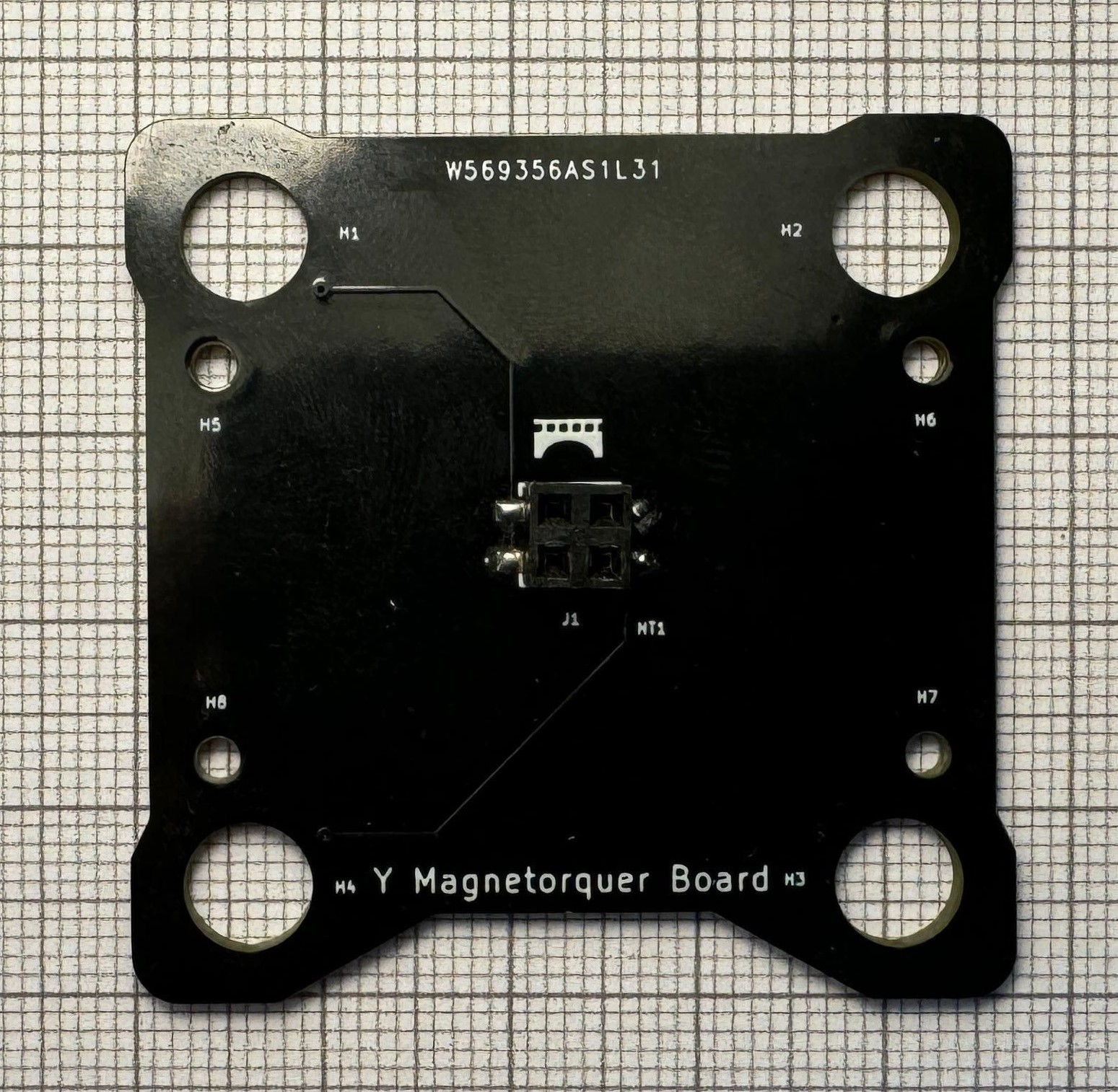](https://wiki.nanosatlab.space/uploads/images/gallery/2024-05/y-mag-pcb.jpeg) | |
| STRUC-4 | Bottom board. | 1 | Bottom board with 2 killswitches, umbilical connector, photodiode and solar cell installed.
Board design may be subject to small modifications. [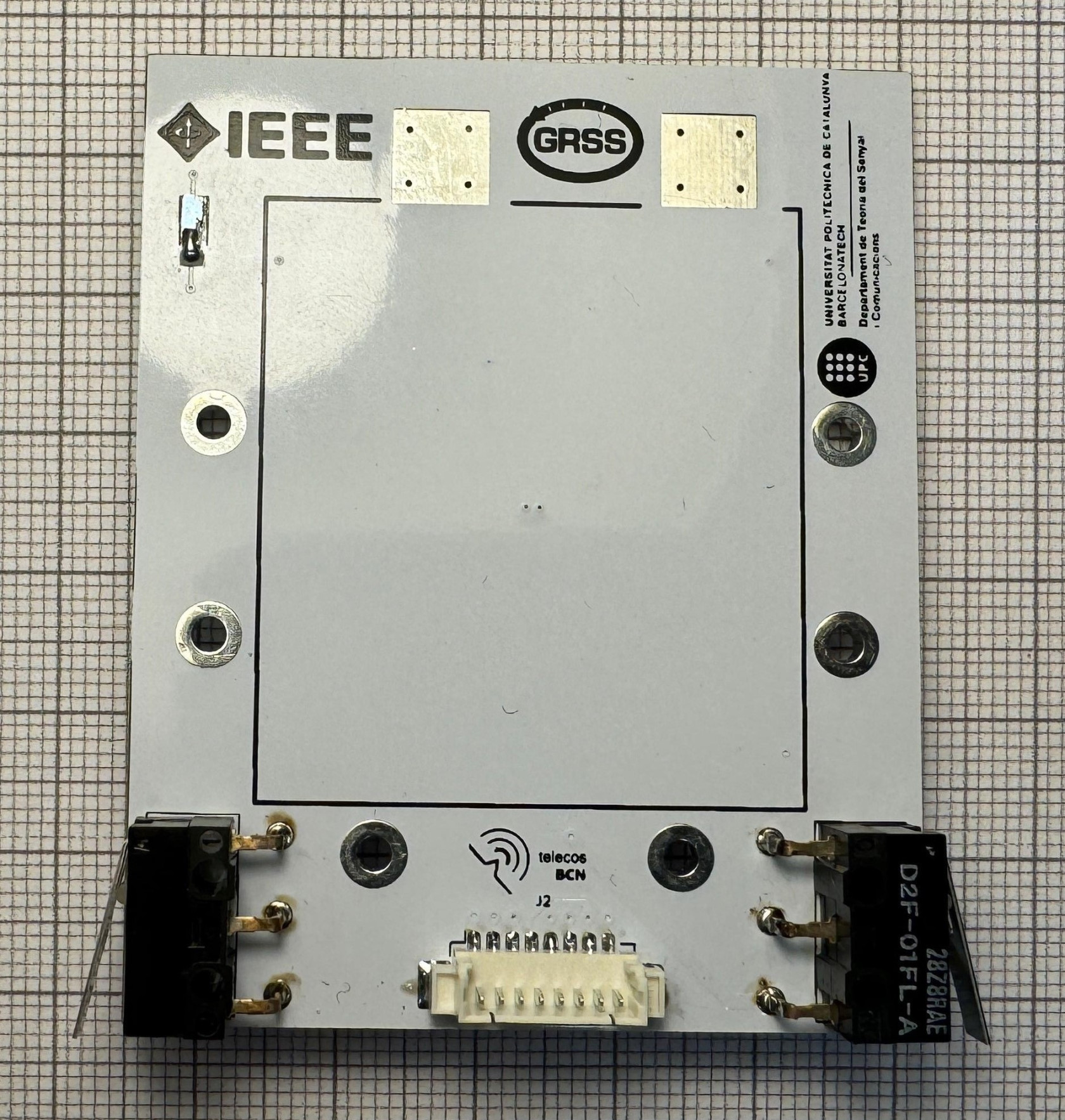](https://wiki.nanosatlab.space/uploads/images/gallery/2024-05/bot-board-bot-view.jpeg) | |
| STRUC-5 | Sliding plate. | 1 | [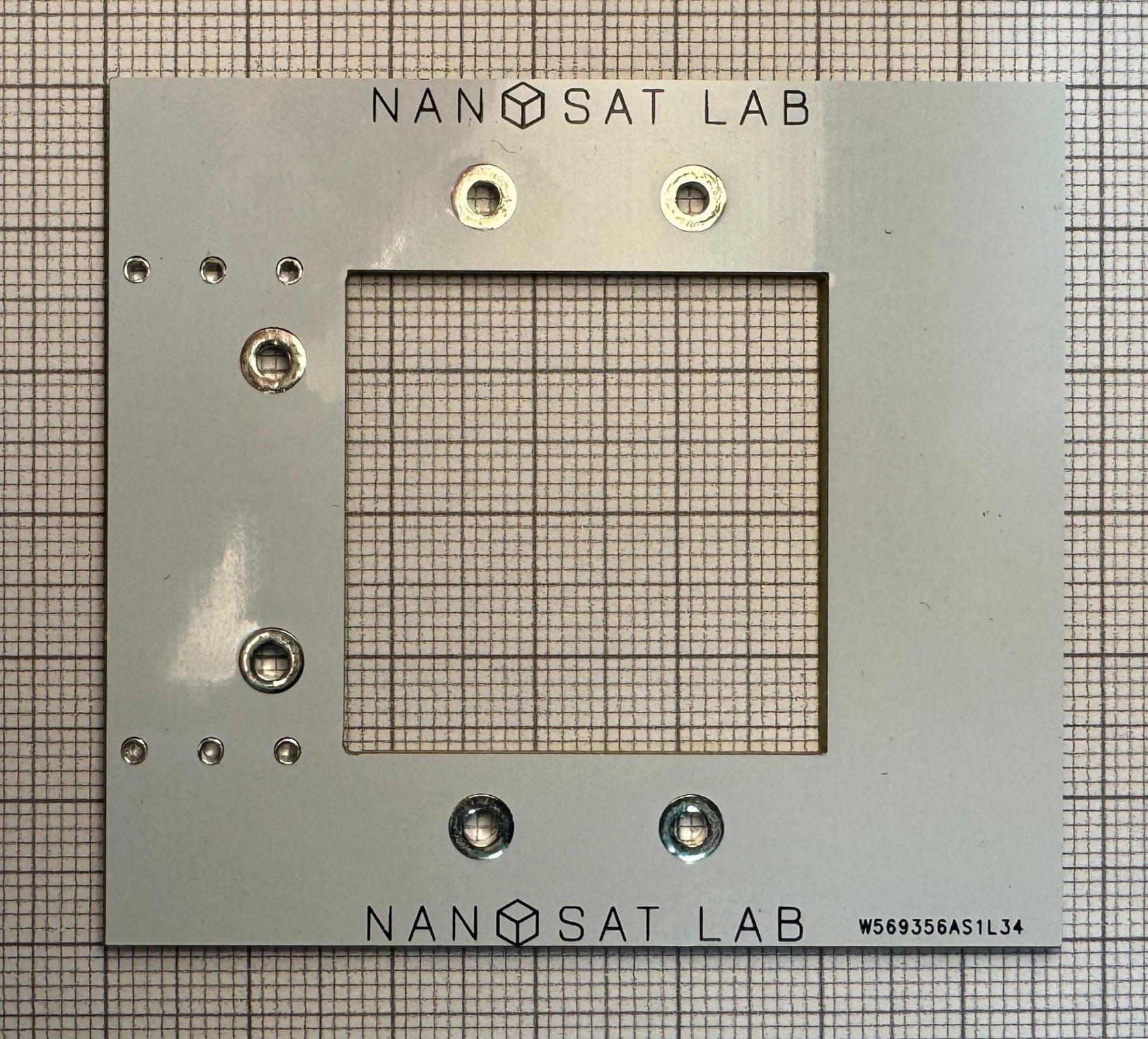](https://wiki.nanosatlab.space/uploads/images/gallery/2024-05/botnotsobot.jpeg) | |
| STRUC-6 | Lateral board. | 3 | Lateral board with installed photodiode and temperature sensor.
Board design may be subject to small modifications. [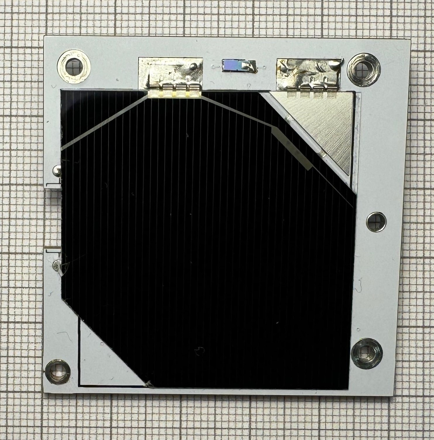](https://wiki.nanosatlab.space/uploads/images/gallery/2024-05/lat-board-solar-view.jpeg)[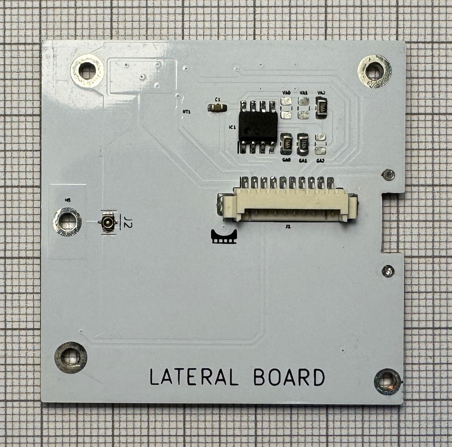](https://wiki.nanosatlab.space/uploads/images/gallery/2024-05/zGelat-board-inner-view.jpeg) | |
| STRUC-7 | Lateral board with antenna. | 1 | Lateral board with installed antenna, low impedance resistor, photodiode and temperature sensor.
Board design may be subject to small modifications. [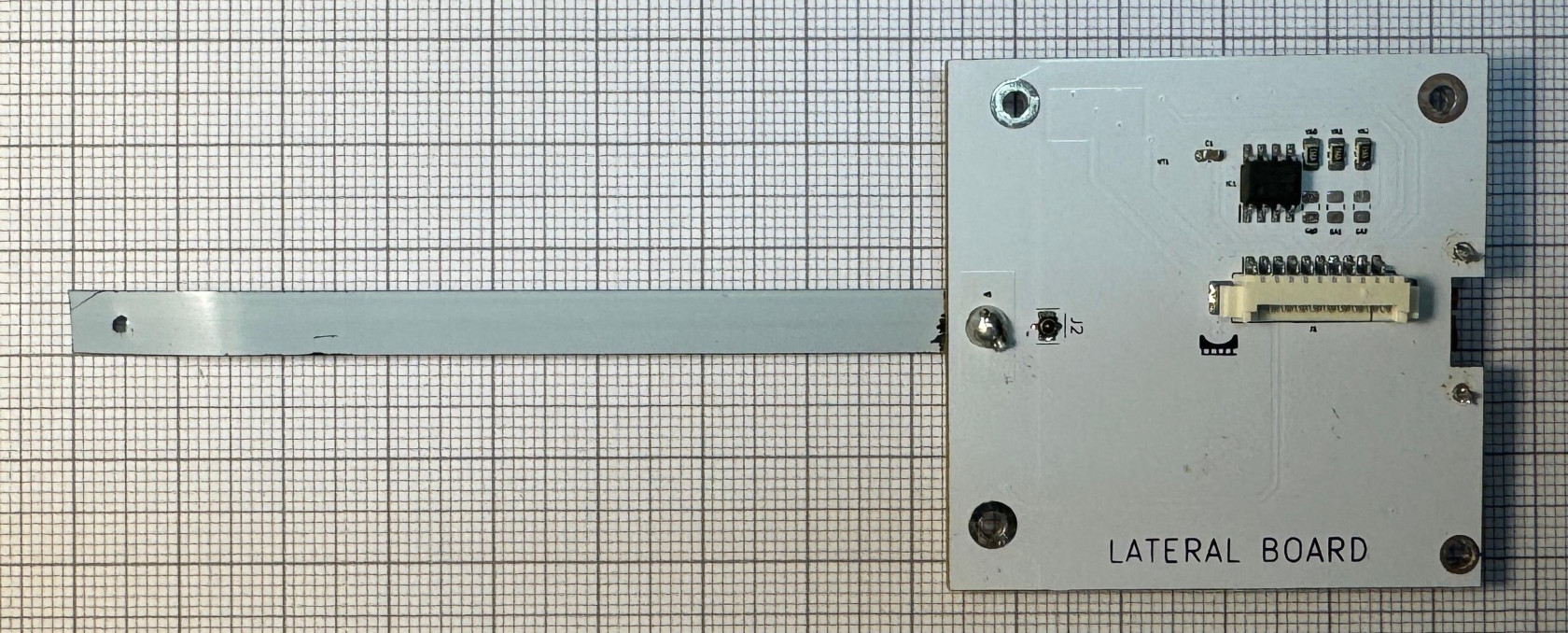](https://wiki.nanosatlab.space/uploads/images/gallery/2024-05/lat-board-antenna-inner-view.jpeg) [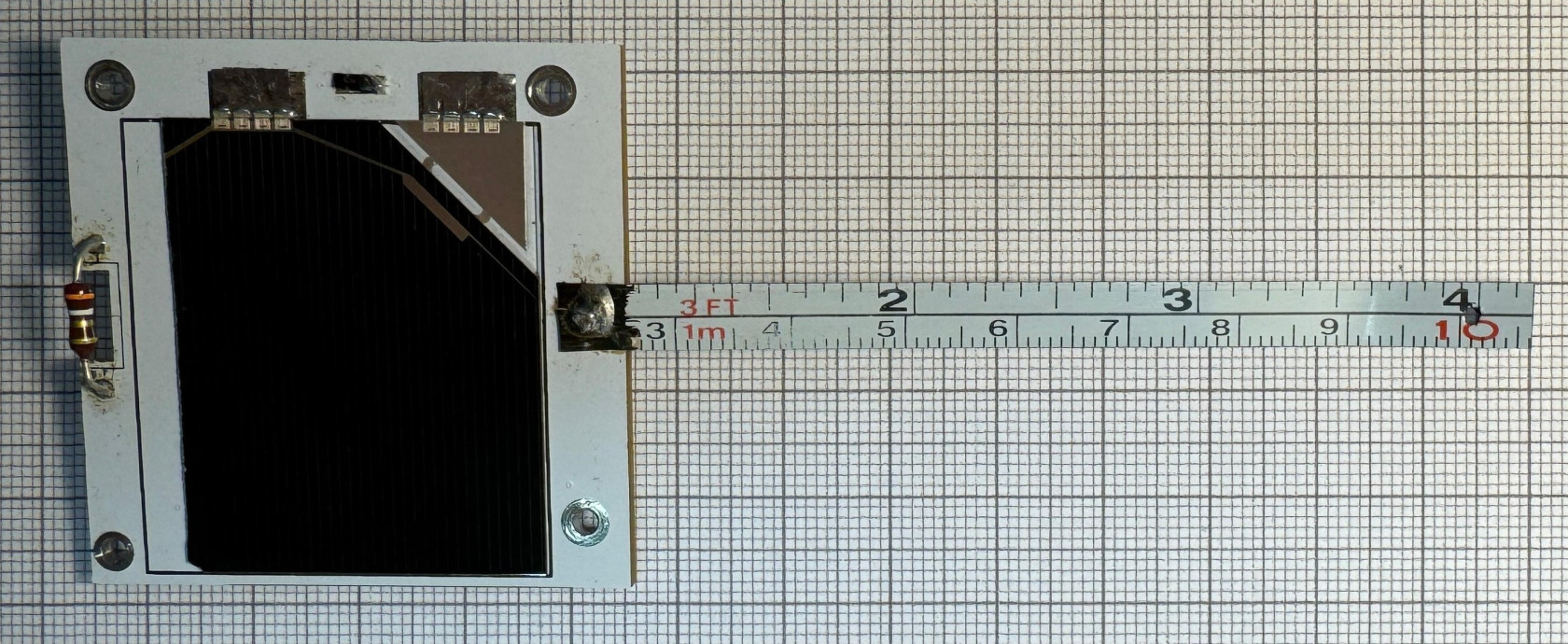](https://wiki.nanosatlab.space/uploads/images/gallery/2024-05/lat-board-antenna-solar-view.jpeg) | |
| Dyneema | 1 | UHMPE 0.35mm diameter, 26 kg [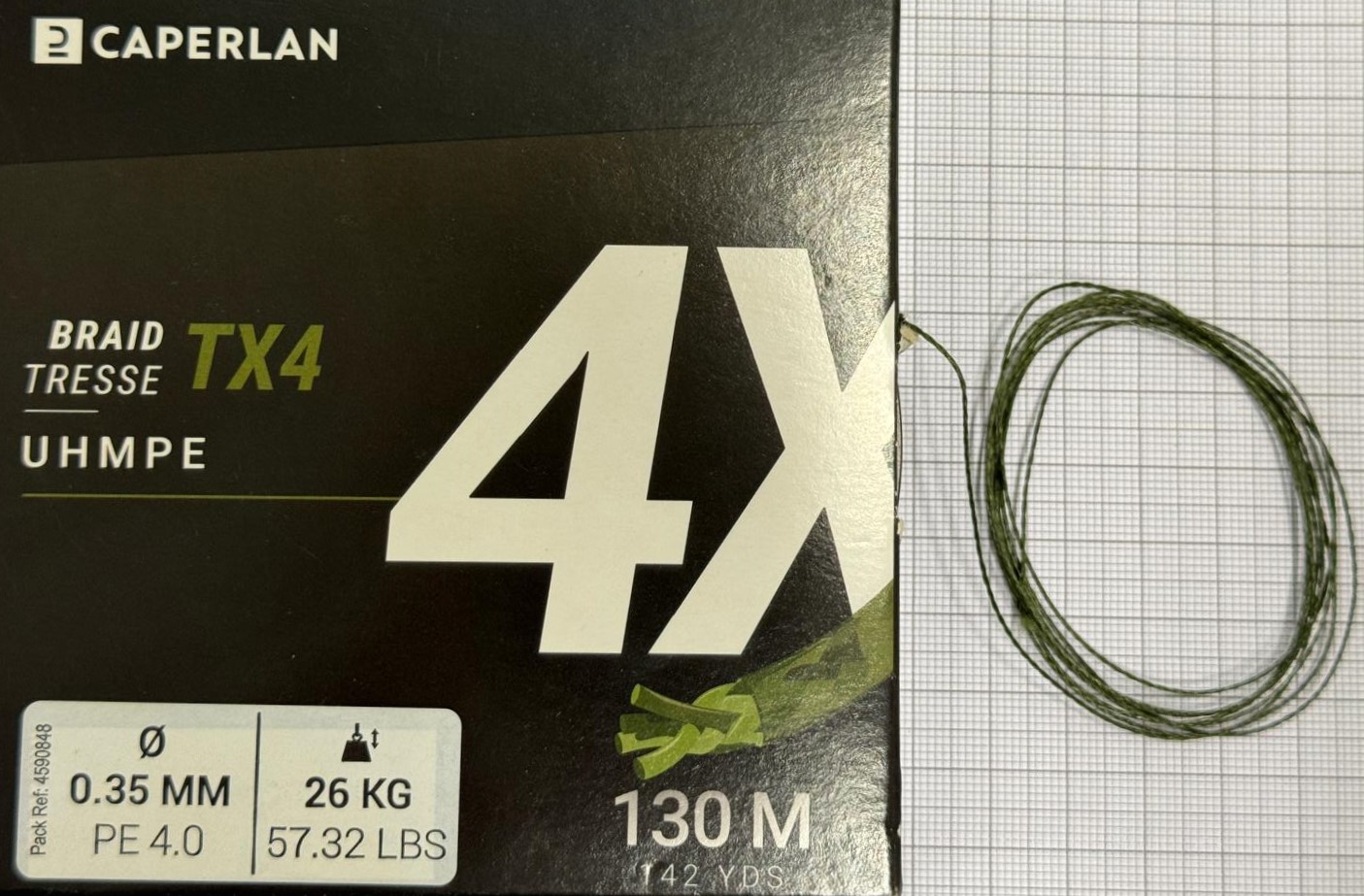](https://wiki.nanosatlab.space/uploads/images/gallery/2024-05/KEmwhatsapp-image-2024-05-06-at-11-15-02.jpeg) |
| **Step** | **Materials** | **Description** | **Remarks/Requirements to be met** | **Carpeta fotos** |
| 10 | 1 x Complete bottom structure including battery and the other components | Prepare bottom structure for assembly. | - Confirm that the bottom structure assembly instructions have been correctly followed before proceeding. | [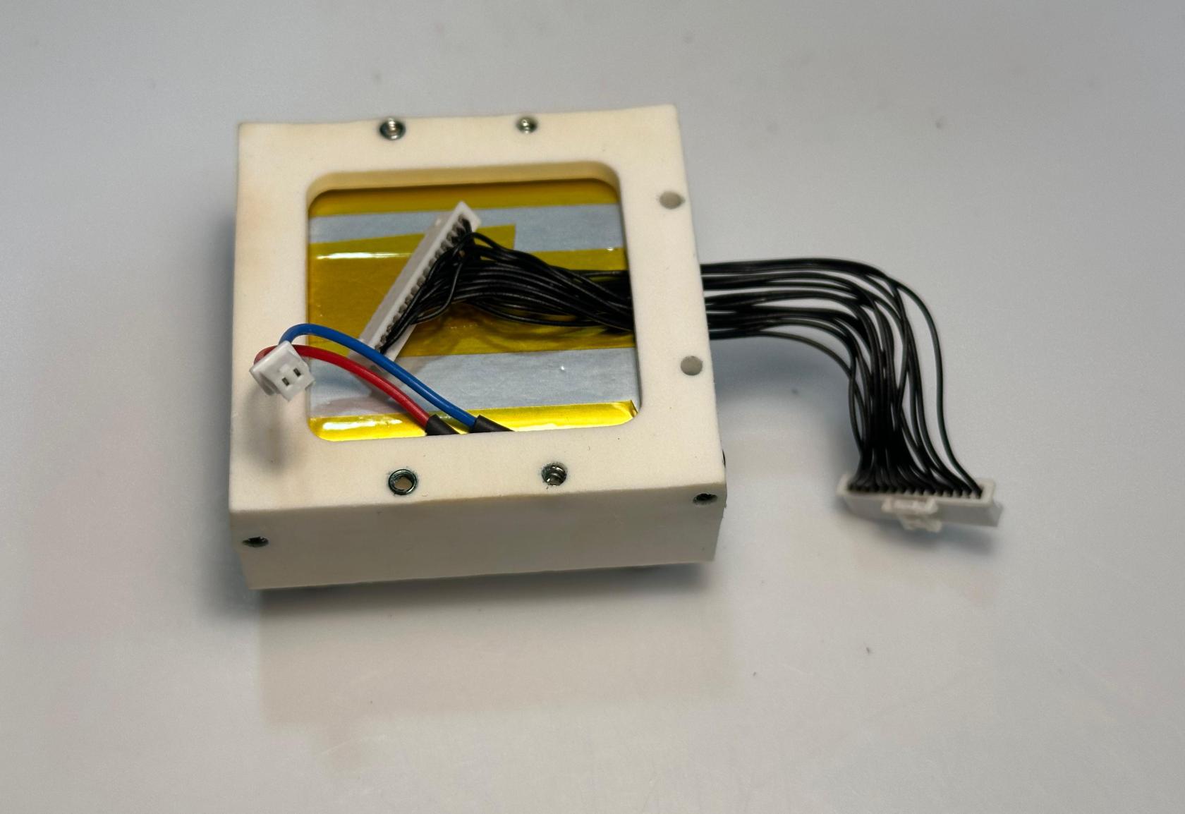](https://wiki.nanosatlab.space/uploads/images/gallery/2025-07/QXCwhatsapp-image-2024-11-06-at-18-54-16-1.jpeg) [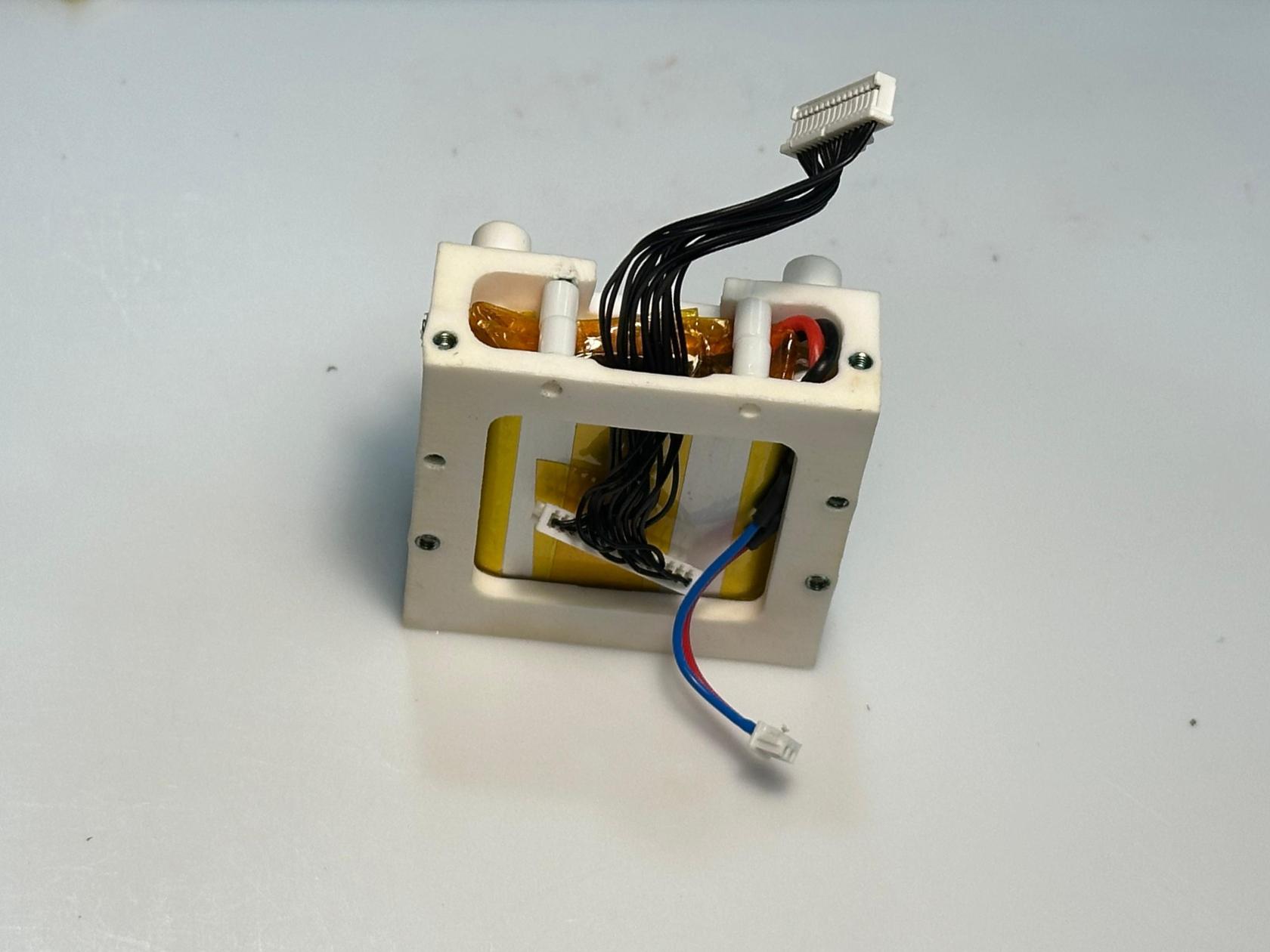](https://wiki.nanosatlab.space/uploads/images/gallery/2025-07/T6fwhatsapp-image-2024-11-06-at-18-54-16.jpeg) |
| 20 | 1 x Kapton 1 x PCB-01 | Install kapton to ensure the killswitches remain closed during the assembly. | \- Ensure that the killswitches are fully pressed.
\- The bottom solar cell has been installed according to the specific tutorial; refer to it for more information.
Add reference to SC assembly. | [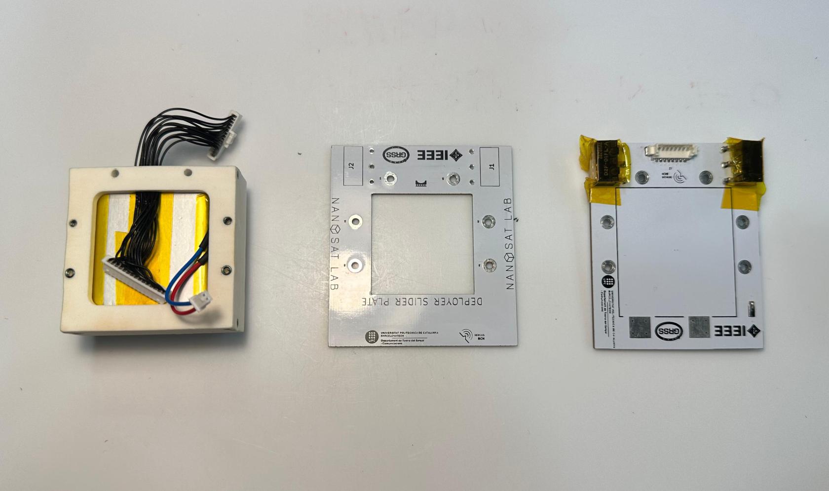](https://wiki.nanosatlab.space/uploads/images/gallery/2025-07/whatsapp-image-2024-11-06-at-19-04-55-1.jpeg) |
| 30 | 1 x PCB-01 1 x PCB-02 1 x Bottom structure 4 x SPACER-01 4 x SCREW-01 2 x SCREW-02 | Prepare the components. | [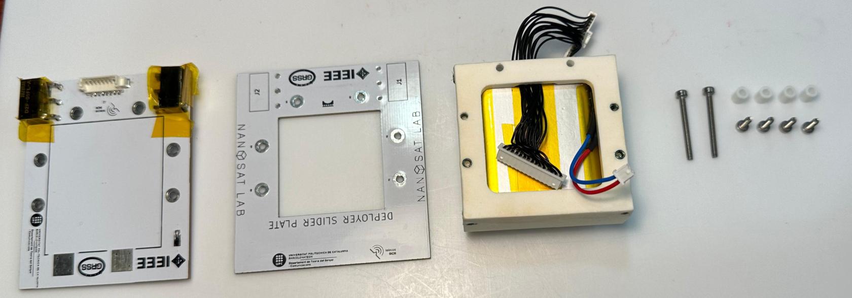](https://wiki.nanosatlab.space/uploads/images/gallery/2025-07/whatsapp-image-2024-11-06-at-19-14-20.jpeg) | |
| 31 | 1 x PCB-01 1 x PCB-02 | Align and join PCB-01 and PCB-02, ensuring that both the screw holes and killswitch pin holes are properly aligned. | [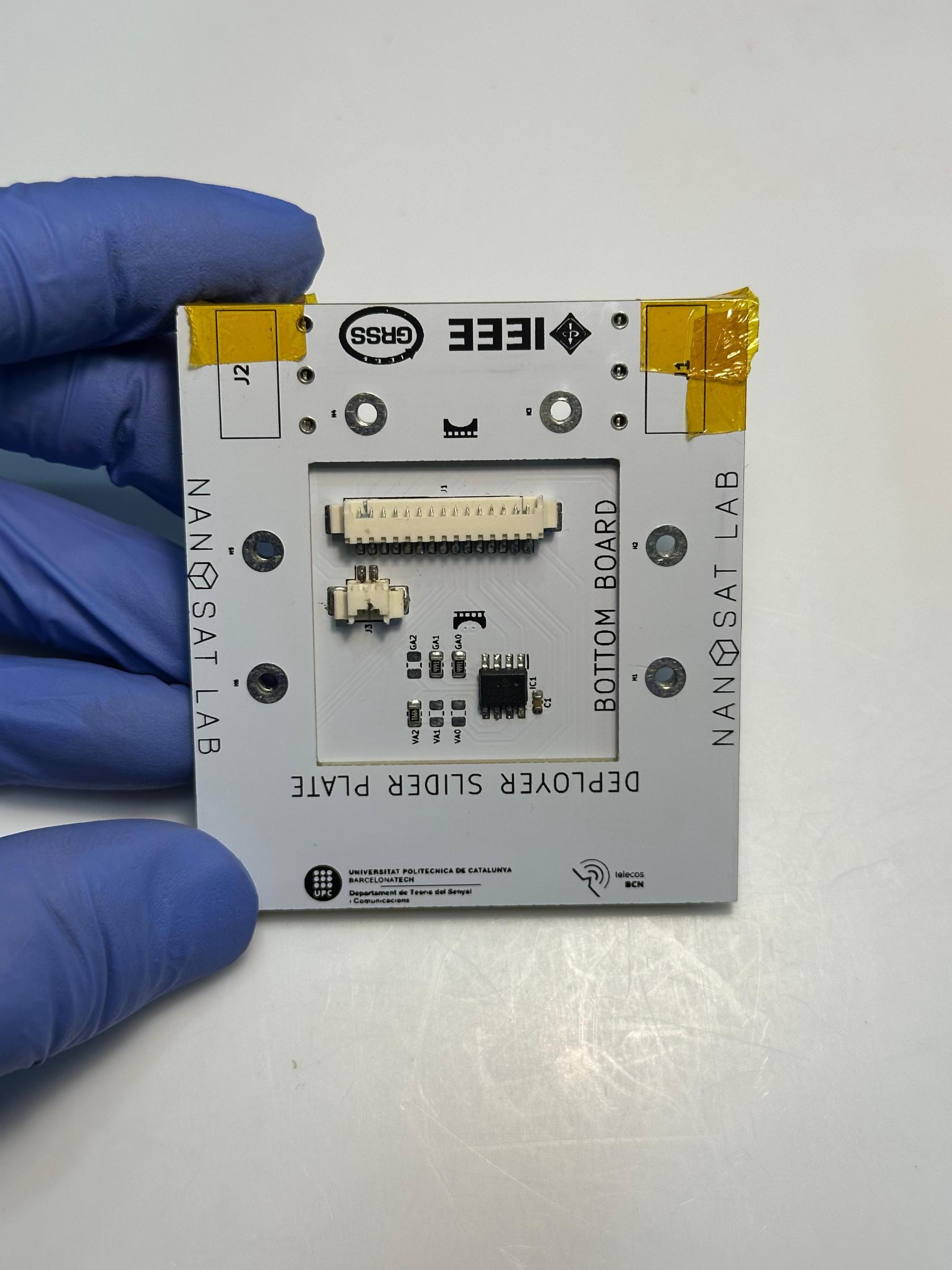](https://wiki.nanosatlab.space/uploads/images/gallery/2025-07/whatsapp-image-2024-11-06-at-19-17-40.jpeg) [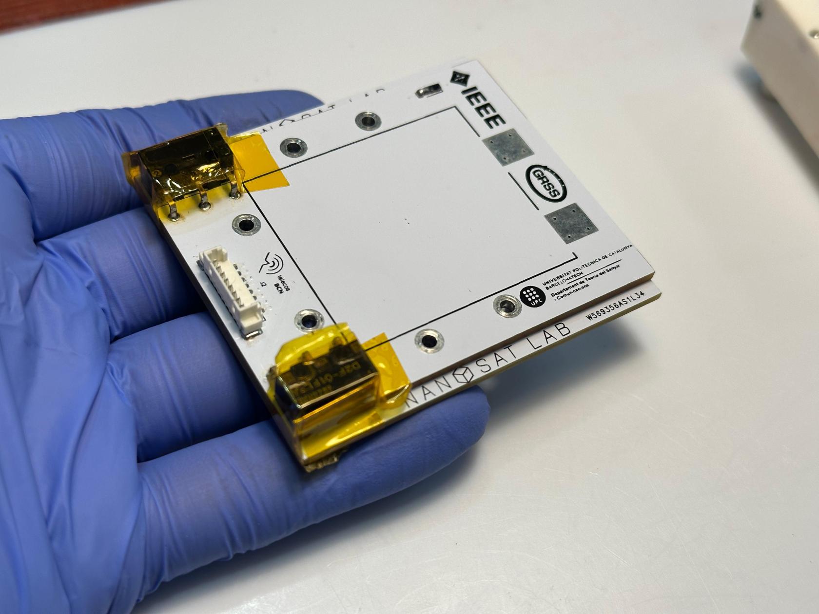](https://wiki.nanosatlab.space/uploads/images/gallery/2025-07/whatsapp-image-2024-11-06-at-19-17-41.jpeg) | |
| 32 | 1 x Bottom structure Recall step 31 | \- Connect the fifteenth picoblade connector from the bottom structure to the connector on PCB-01 that is visible through the PCB-02 aperture. - Connect the battery picoblade to the picoblade pins visible through the PCB-02 aperture. | Ensure proper pin connection. | [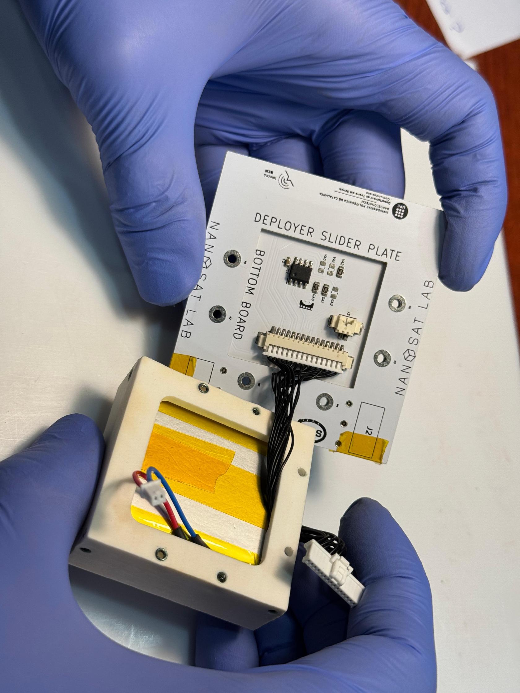](https://wiki.nanosatlab.space/uploads/images/gallery/2025-07/whatsapp-image-2024-11-06-at-19-22-47-1.jpeg) [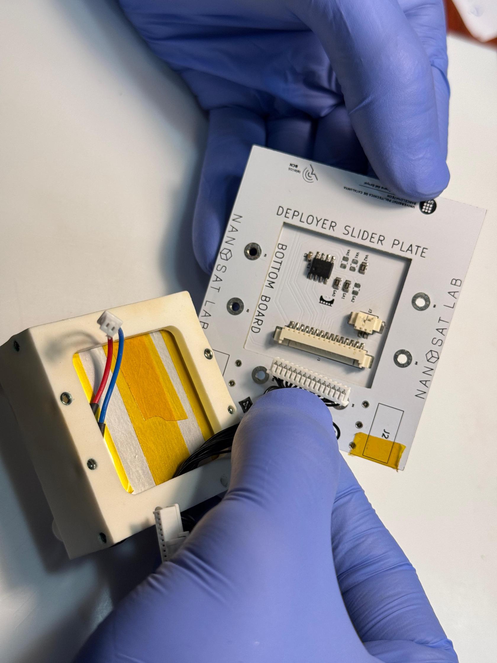](https://wiki.nanosatlab.space/uploads/images/gallery/2025-07/whatsapp-image-2024-11-06-at-19-22-47.jpeg) [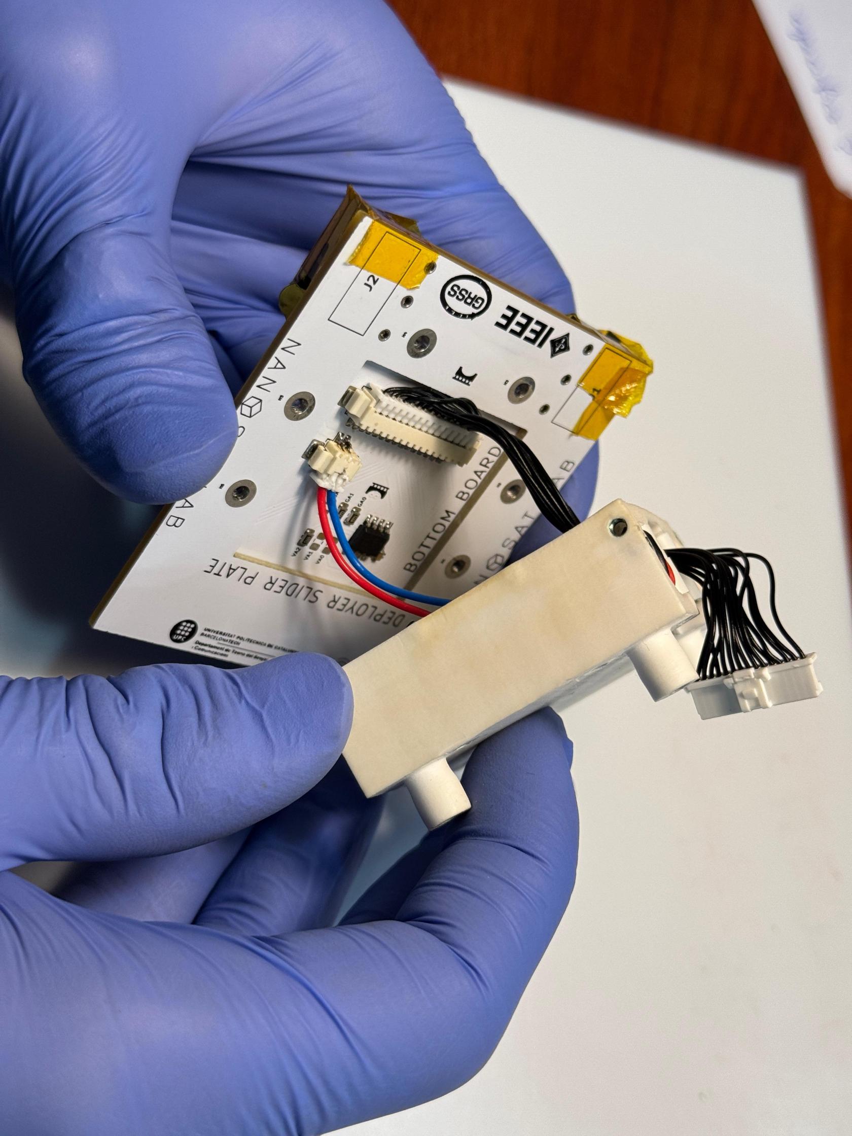](https://wiki.nanosatlab.space/uploads/images/gallery/2025-07/whatsapp-image-2024-11-06-at-19-24-36.jpeg) |
| 33 | Recall step 32 | Once the battery picoblade is connected, apply Kapton tape to secure the cable loop to the PCB. | [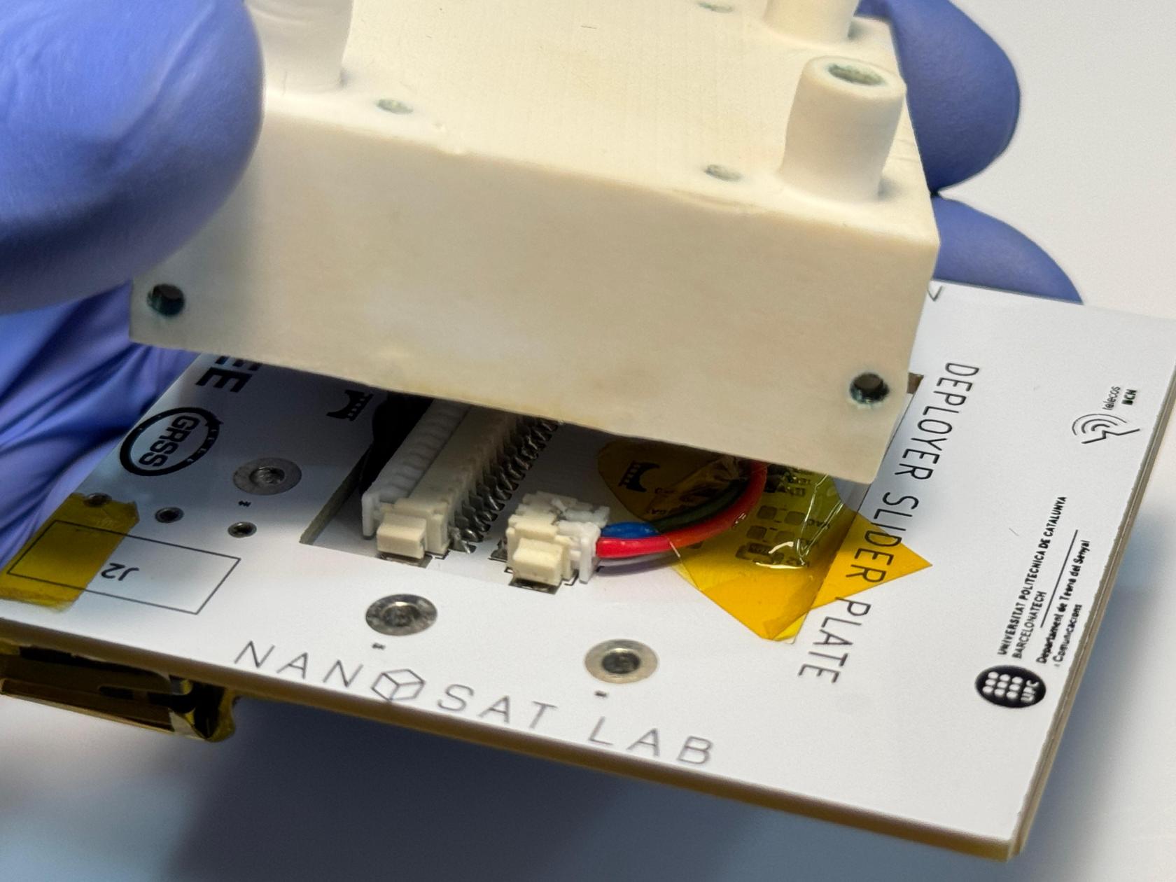](https://wiki.nanosatlab.space/uploads/images/gallery/2025-07/whatsapp-image-2024-11-06-at-19-37-09.jpeg) | |
| 34 | Recall step 33 | Gently pull the fifteen-pin flatwire through the bottom structure aperture to close the gap between the bottom structure and the PCBs. | \- Ensure that no cables are pinched once the bottom structure and PCBs are joined. - Make sure the battery cable remains inside the aperture with a loop. | [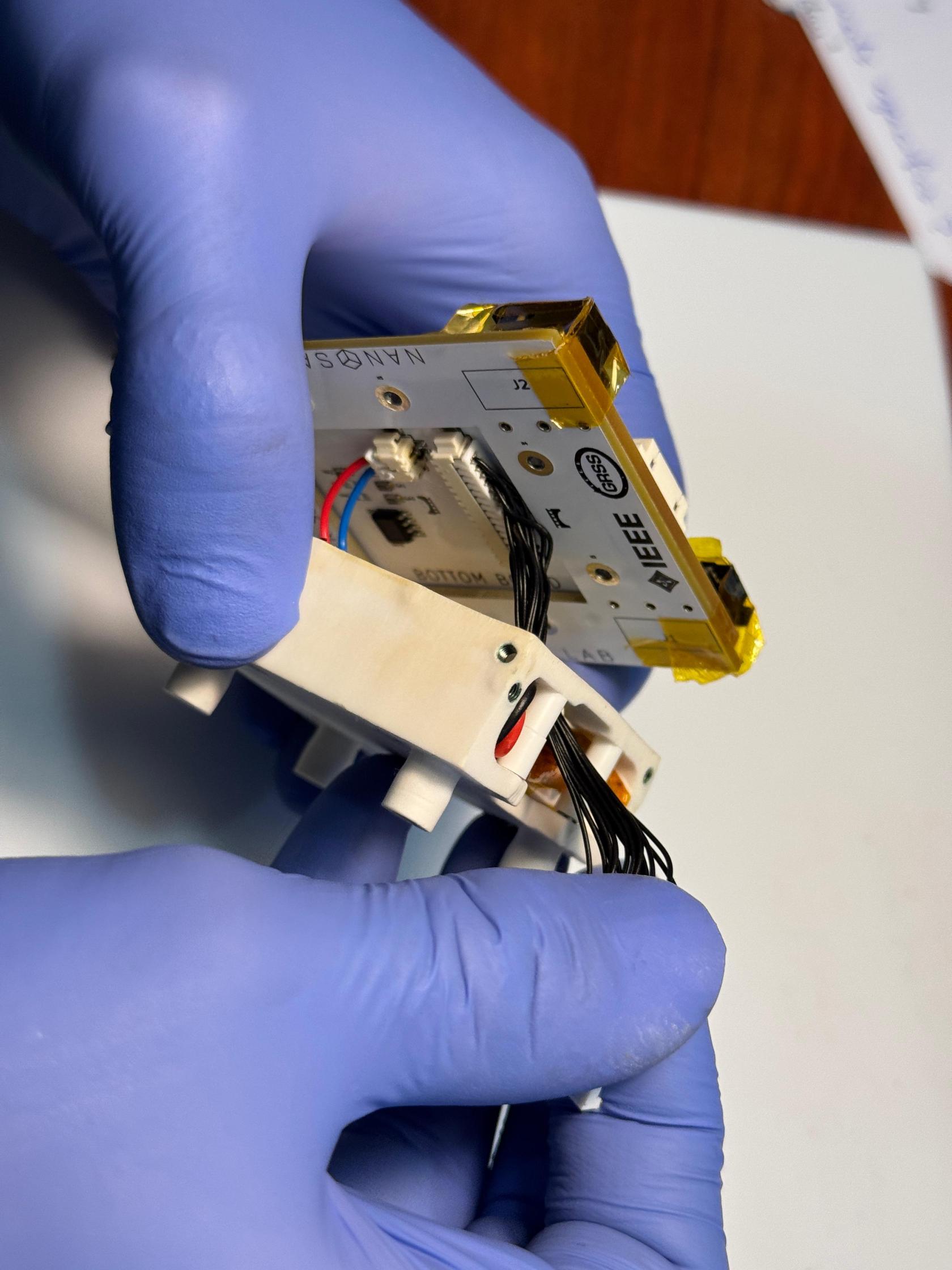](https://wiki.nanosatlab.space/uploads/images/gallery/2025-07/whatsapp-image-2024-11-06-at-19-27-06-1.jpeg) [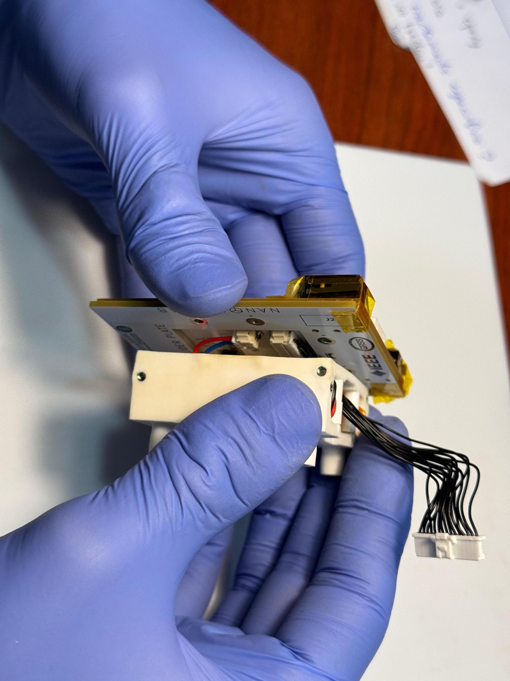](https://wiki.nanosatlab.space/uploads/images/gallery/2025-07/whatsapp-image-2024-11-06-at-19-27-06-4.jpeg) [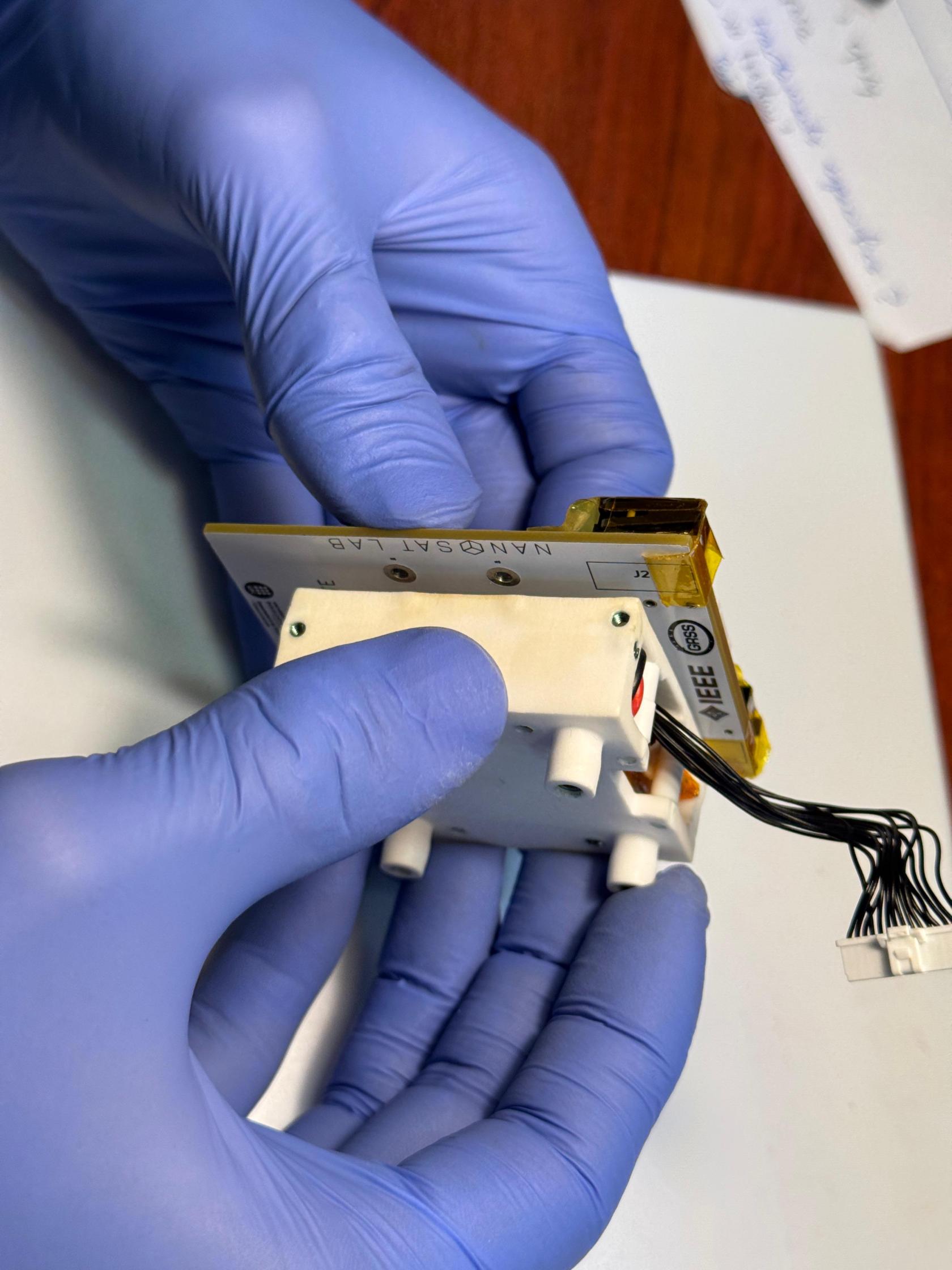](https://wiki.nanosatlab.space/uploads/images/gallery/2025-07/whatsapp-image-2024-11-06-at-19-27-06-5.jpeg) [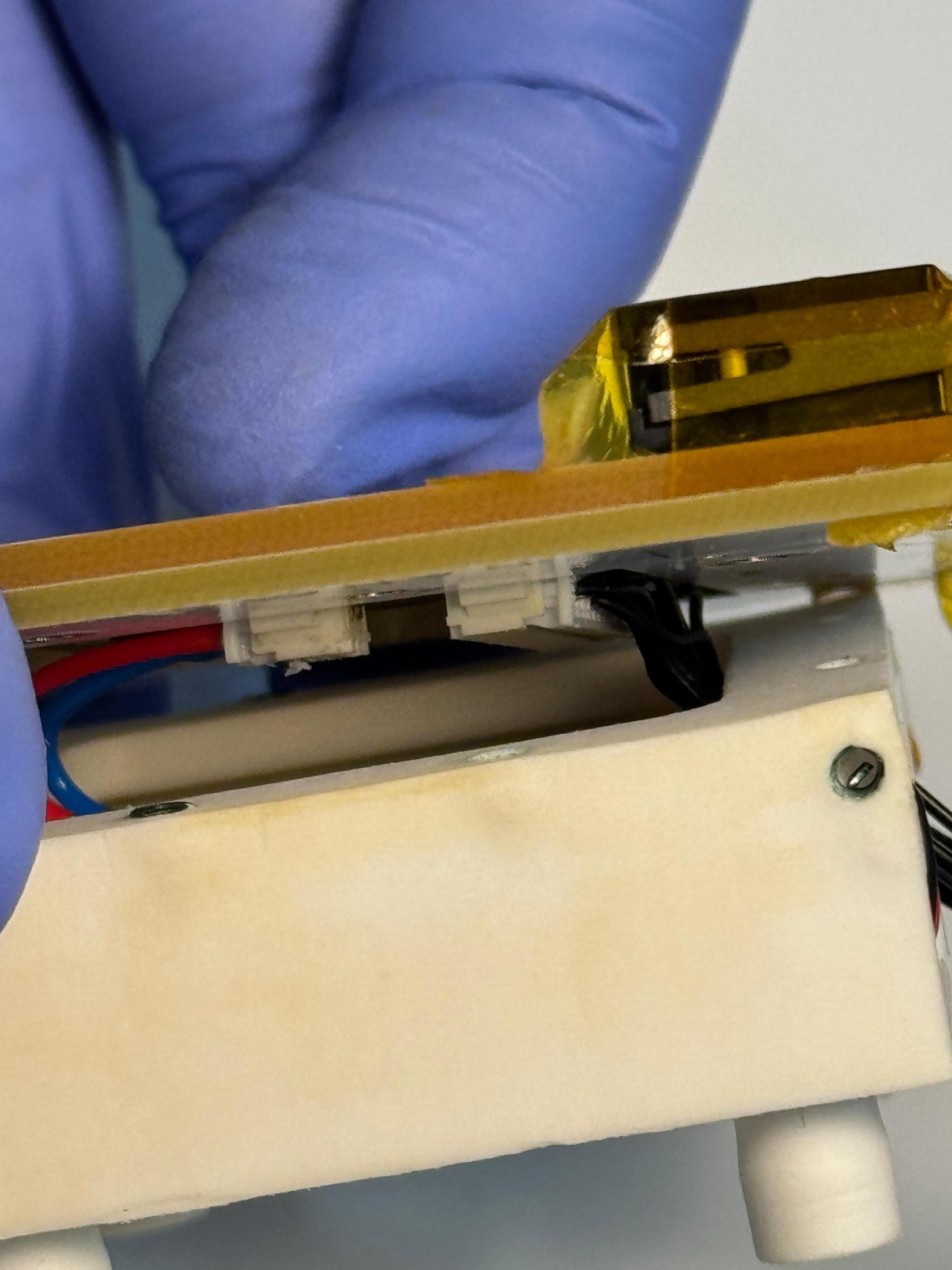](https://wiki.nanosatlab.space/uploads/images/gallery/2025-07/whatsapp-image-2024-11-06-at-19-27-06-6.jpeg) |
| 35 | Recall step 34 | Attach PCB-01 and PCB-02 to the bottom structure. | \- While screwing the screws, hold the bottom structure in place to secure it to the PCBs.
\- Ensure the correct torque is applied.
Add torque | [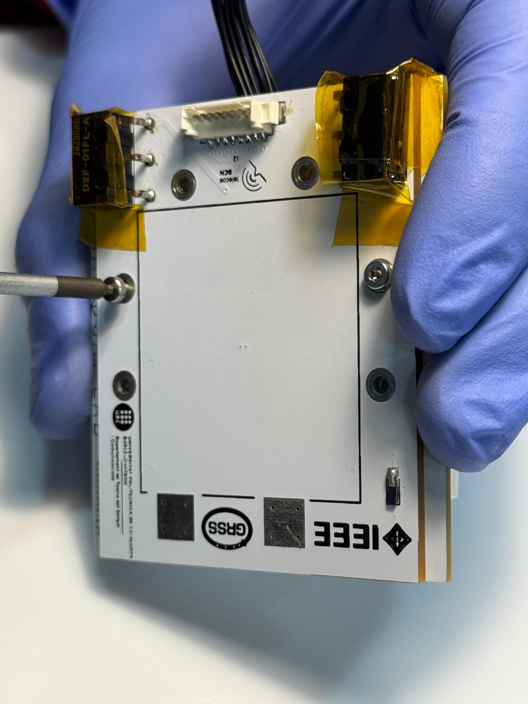](https://wiki.nanosatlab.space/uploads/images/gallery/2025-07/whatsapp-image-2024-11-06-at-19-45-49.jpeg) [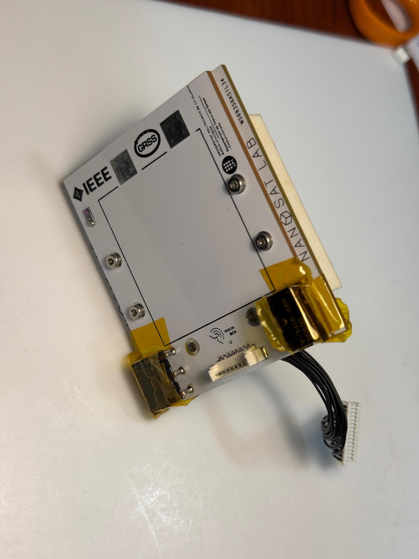](https://wiki.nanosatlab.space/uploads/images/gallery/2025-07/whatsapp-image-2024-11-06-at-19-45-49-1.jpeg) |
| 36 | 4 x SPACER-01 Recall step 35 | Take a pair of SPACER-01 and insert them vertically into the entry space of the bottom structure, ensuring the screw holes align. | If inserting the spacers is challenging, loosen the aperture slightly, ensuring that the integrity of the structure is not compromised. | [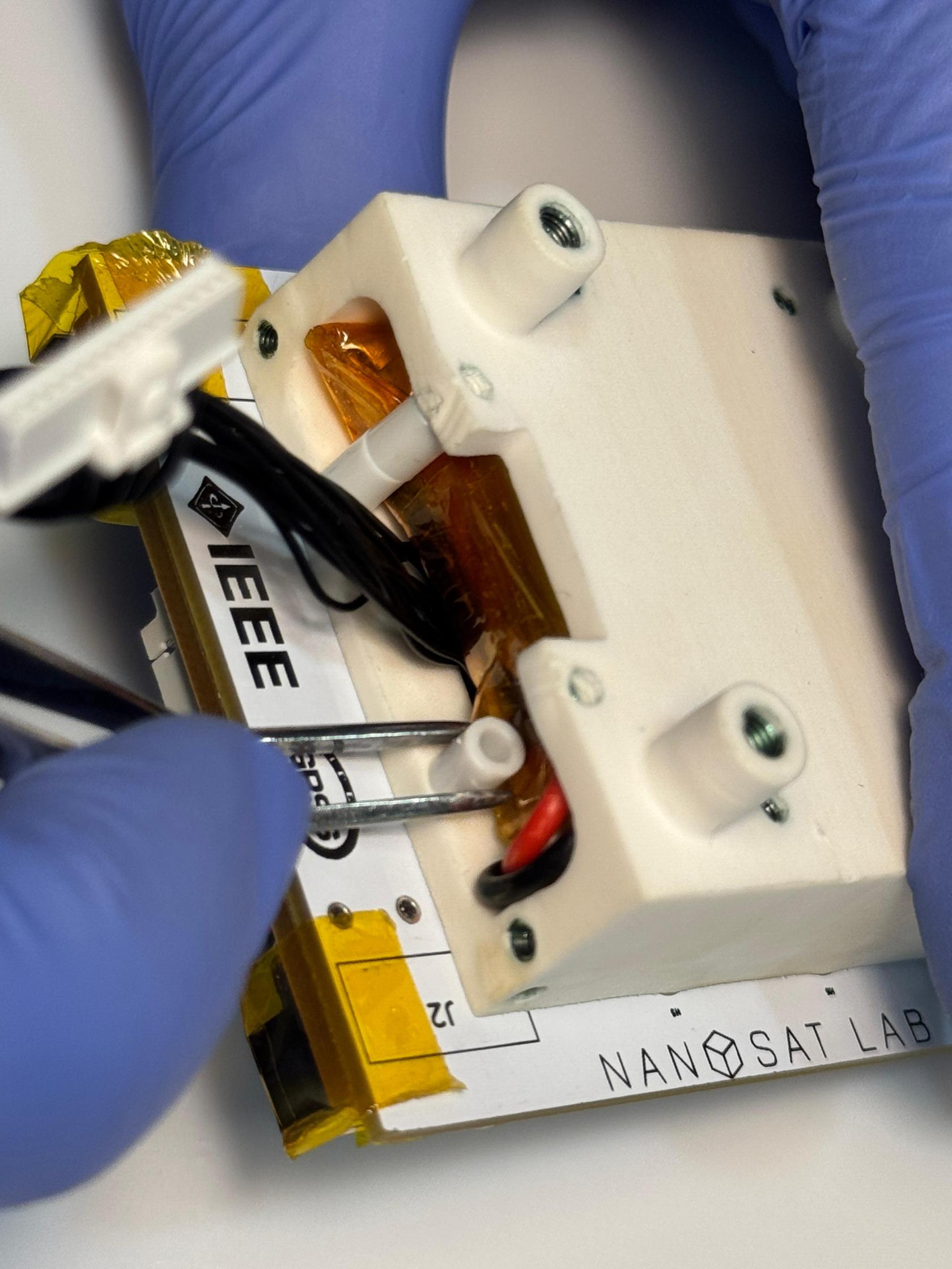](https://wiki.nanosatlab.space/uploads/images/gallery/2025-07/whatsapp-image-2024-11-06-at-19-50-32.jpeg) [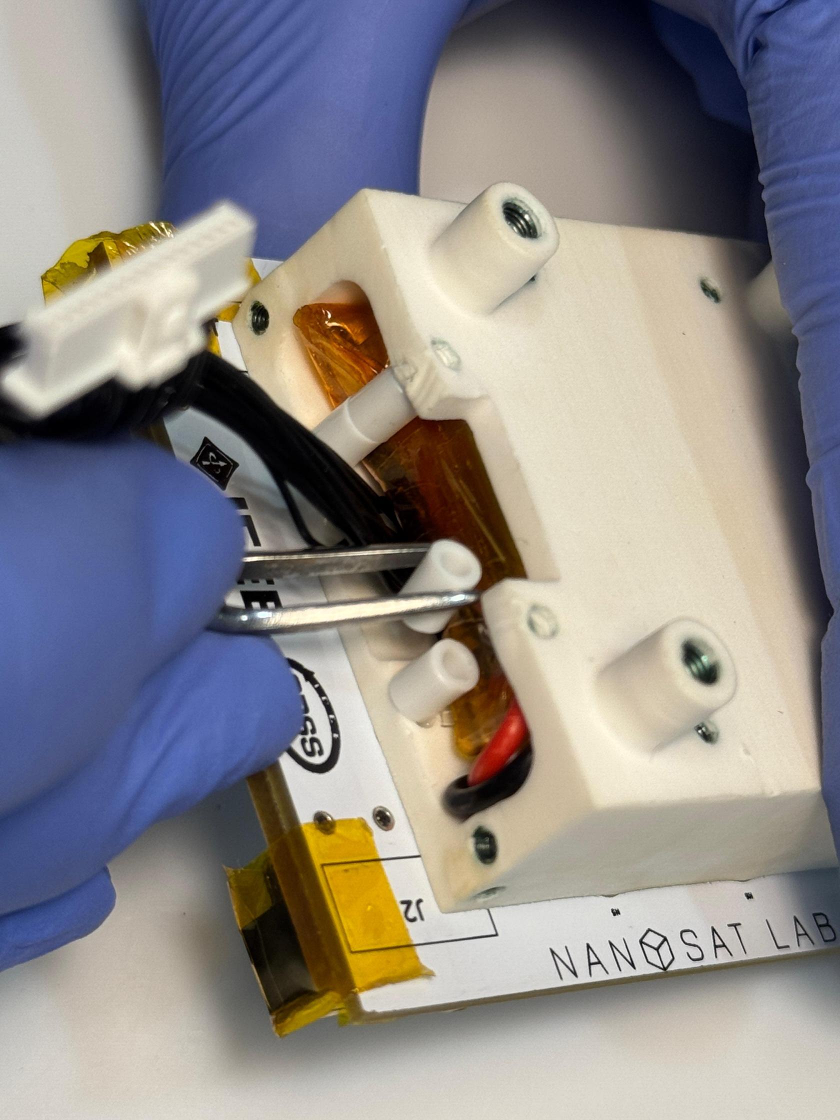](https://wiki.nanosatlab.space/uploads/images/gallery/2025-07/whatsapp-image-2024-11-06-at-19-50-32-1.jpeg) [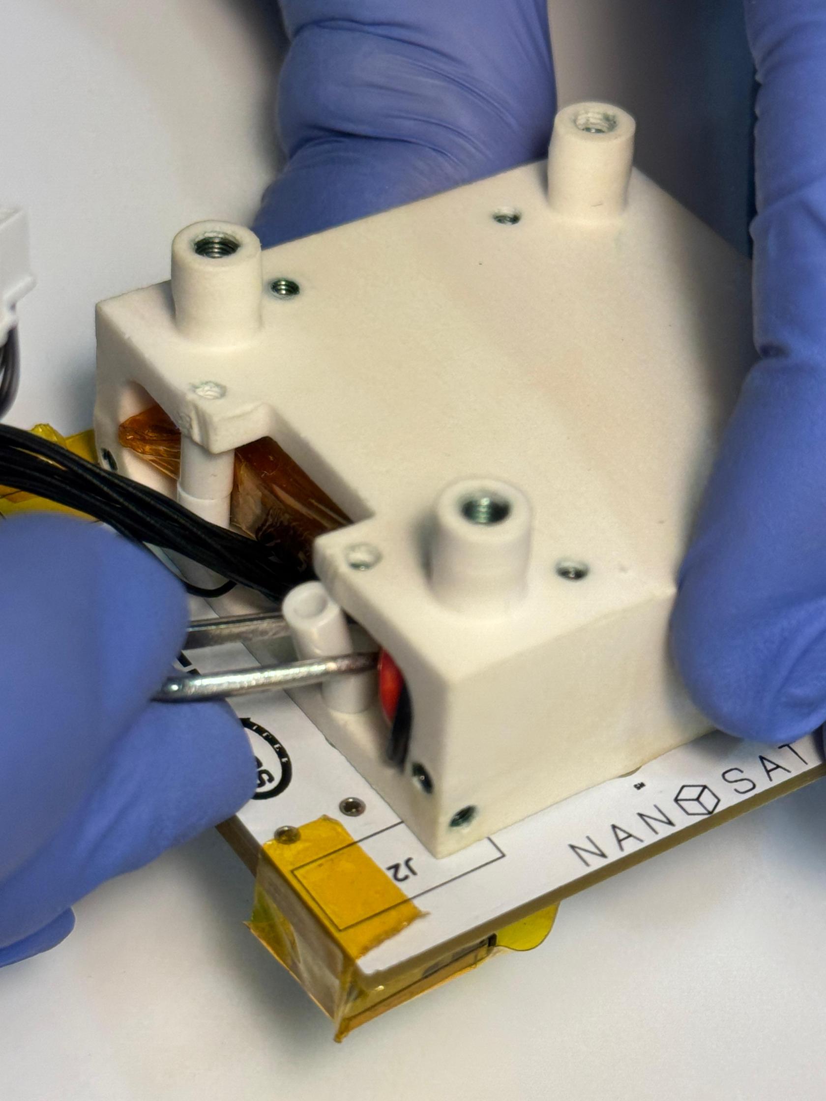](https://wiki.nanosatlab.space/uploads/images/gallery/2025-07/whatsapp-image-2024-11-06-at-19-50-36.jpeg) [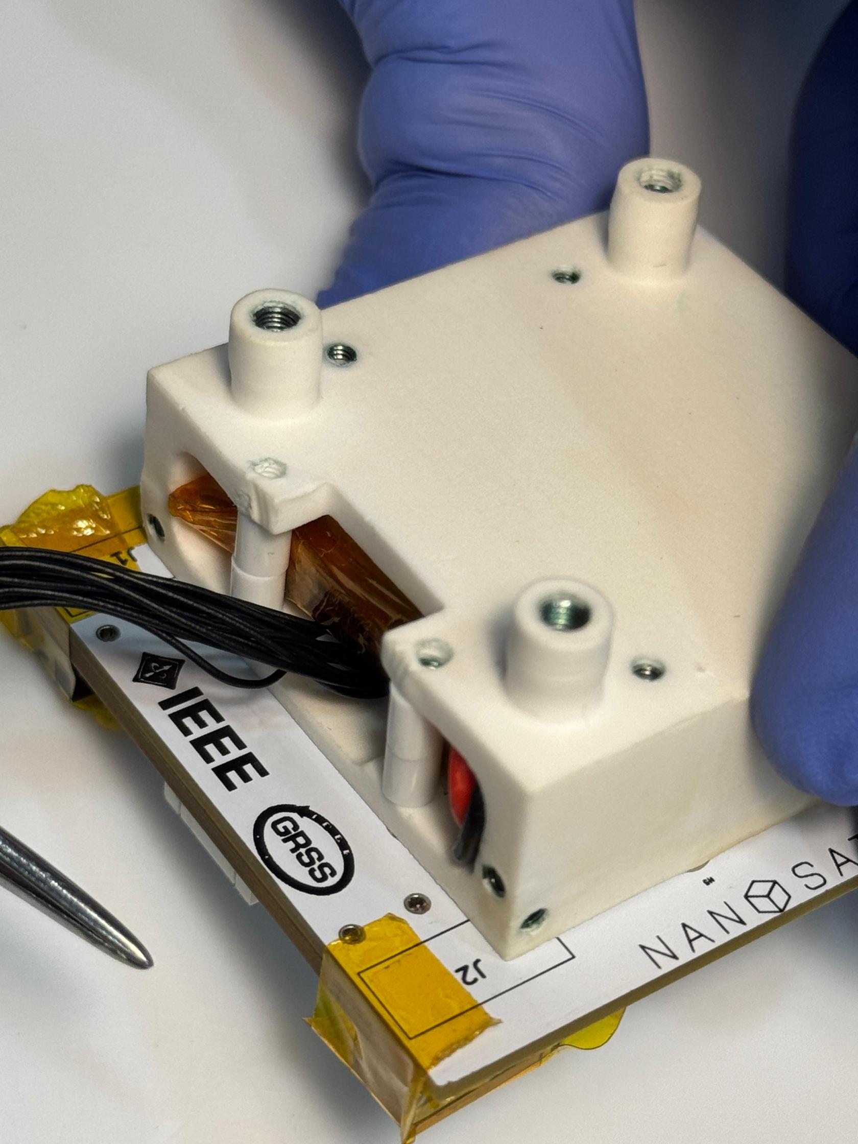](https://wiki.nanosatlab.space/uploads/images/gallery/2025-07/whatsapp-image-2024-11-06-at-19-50-36-1.jpeg) |
| 37 | 2 x SCREW-02 Recall step 36 | Once the holes and spacers are aligned, insert SCREW-02 through PCB-01, PCB-02, the bottom structure, and the pair of SPACER-01 installed in step 36. | [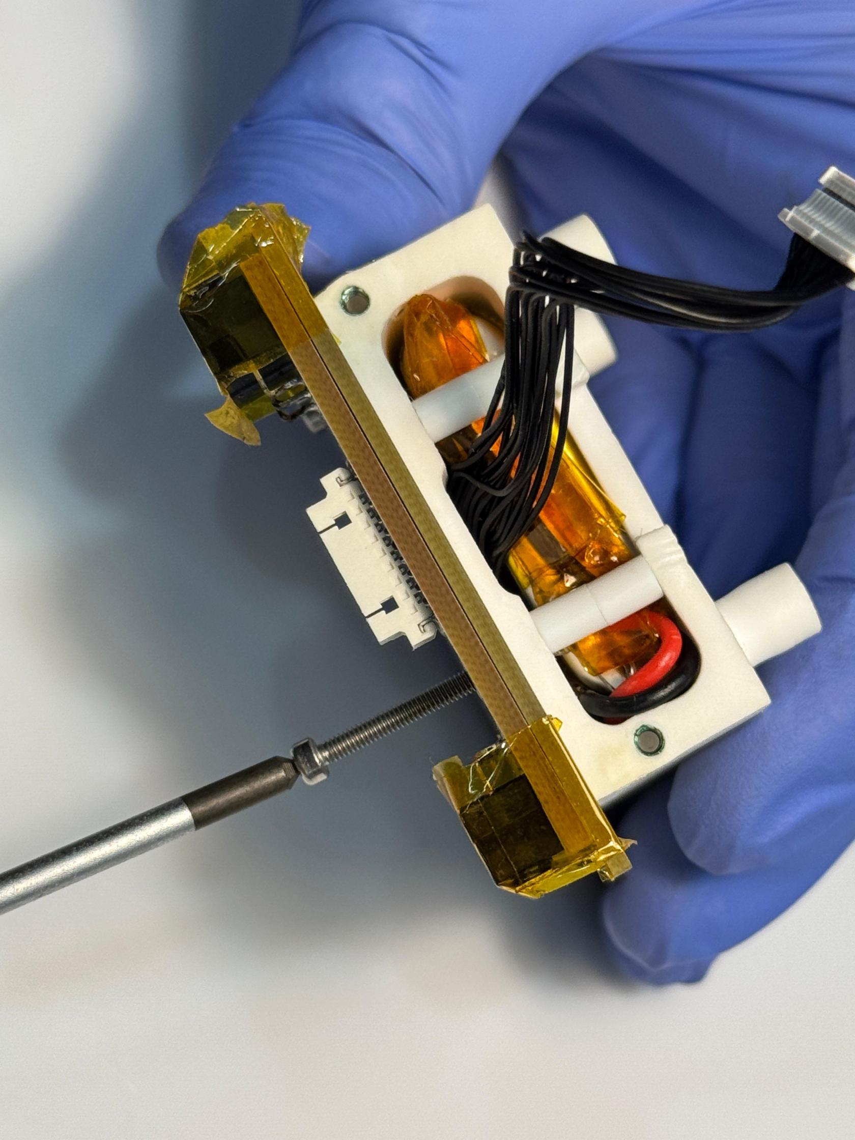](https://wiki.nanosatlab.space/uploads/images/gallery/2025-07/wAzwhatsapp-image-2024-11-06-at-19-50-36.jpeg) [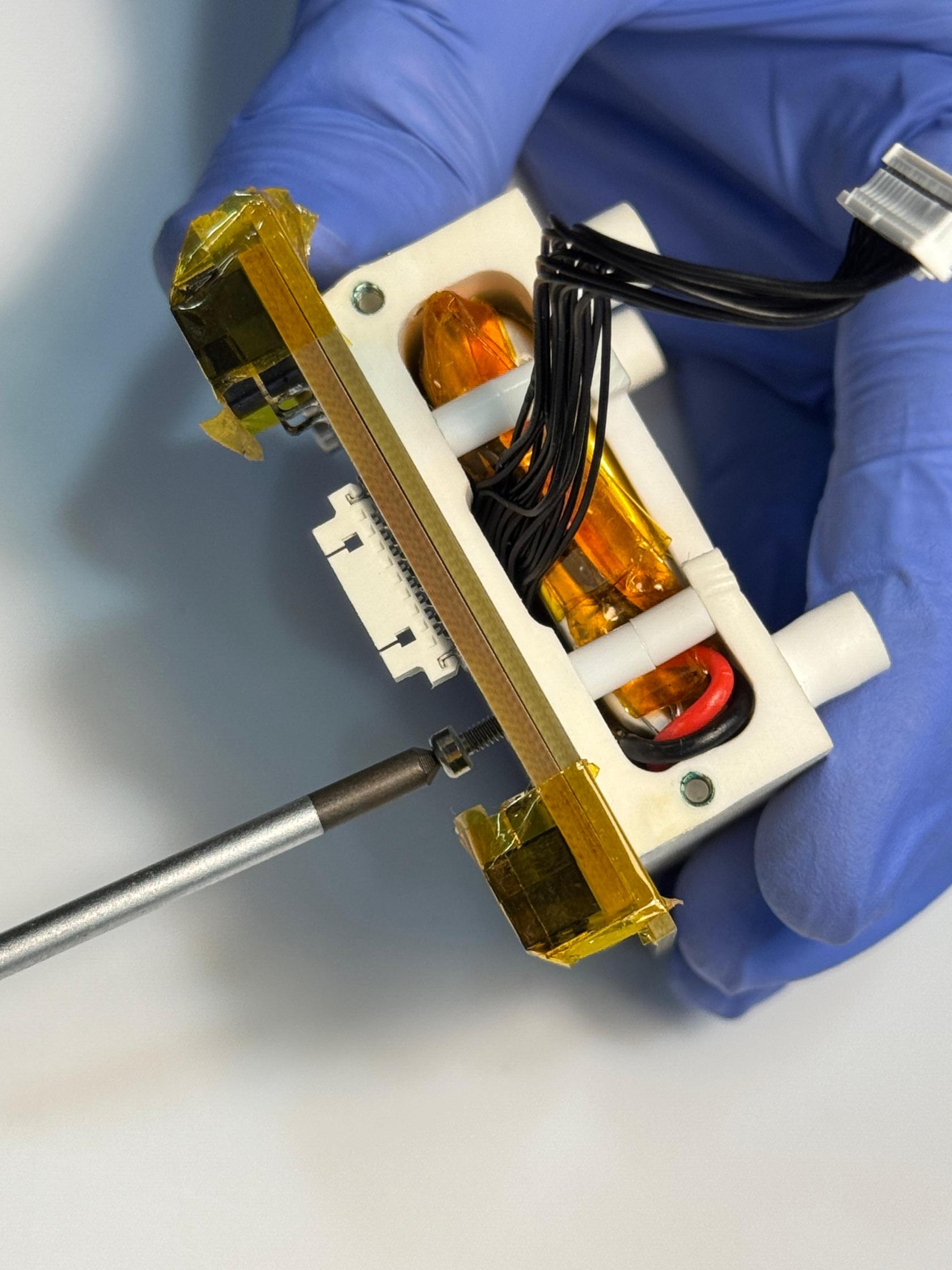](https://wiki.nanosatlab.space/uploads/images/gallery/2025-07/whatsapp-image-2024-11-06-at-19-50-37.jpeg) [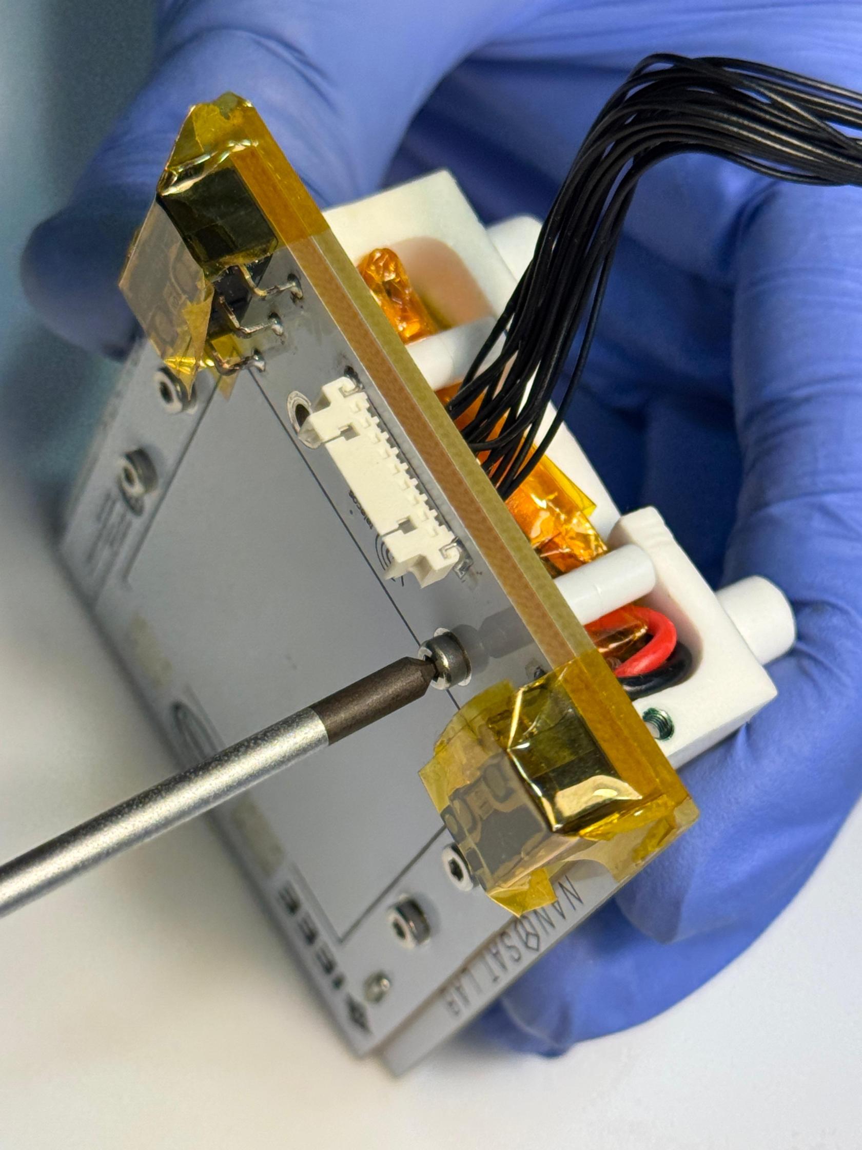](https://wiki.nanosatlab.space/uploads/images/gallery/2025-07/whatsapp-image-2024-11-06-at-19-50-37-1.jpeg) | |
| 38 | Repeat step 36 and 37 with the other pair of spacers. | |||
| 40 | Recall 38 1 x PCB-03 4 x SCREW-03 | Prepare the components. | [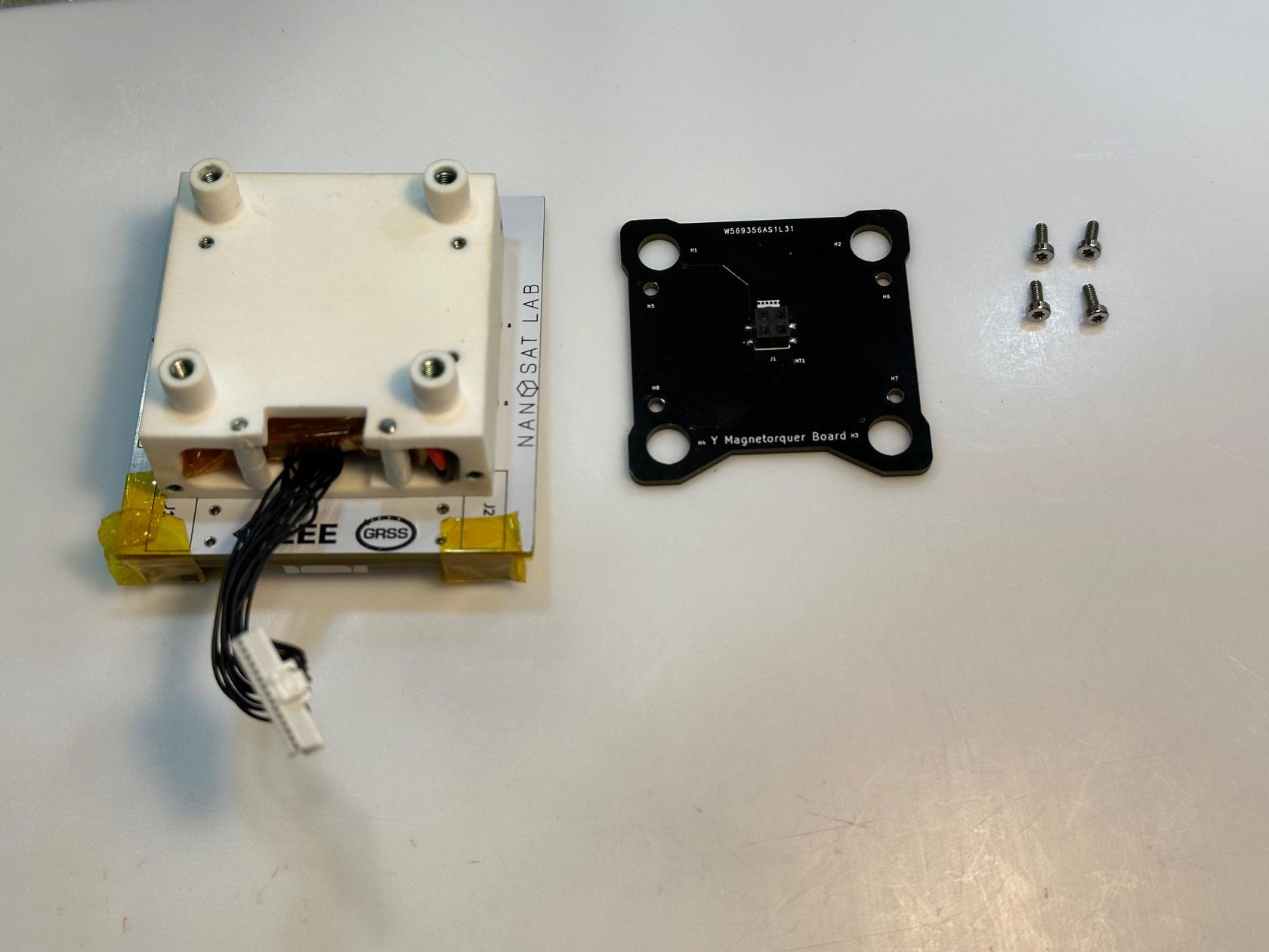](https://wiki.nanosatlab.space/uploads/images/gallery/2025-07/whatsapp-image-2024-11-13-at-17-28-19.jpeg) | |
| 41 | Recall 38 1 x PCB-03 | Position PCB-03 on top of the bottom structure as shown in the image. | Align the battery opening with the magnetorquer aperture as illustrated in the image. | [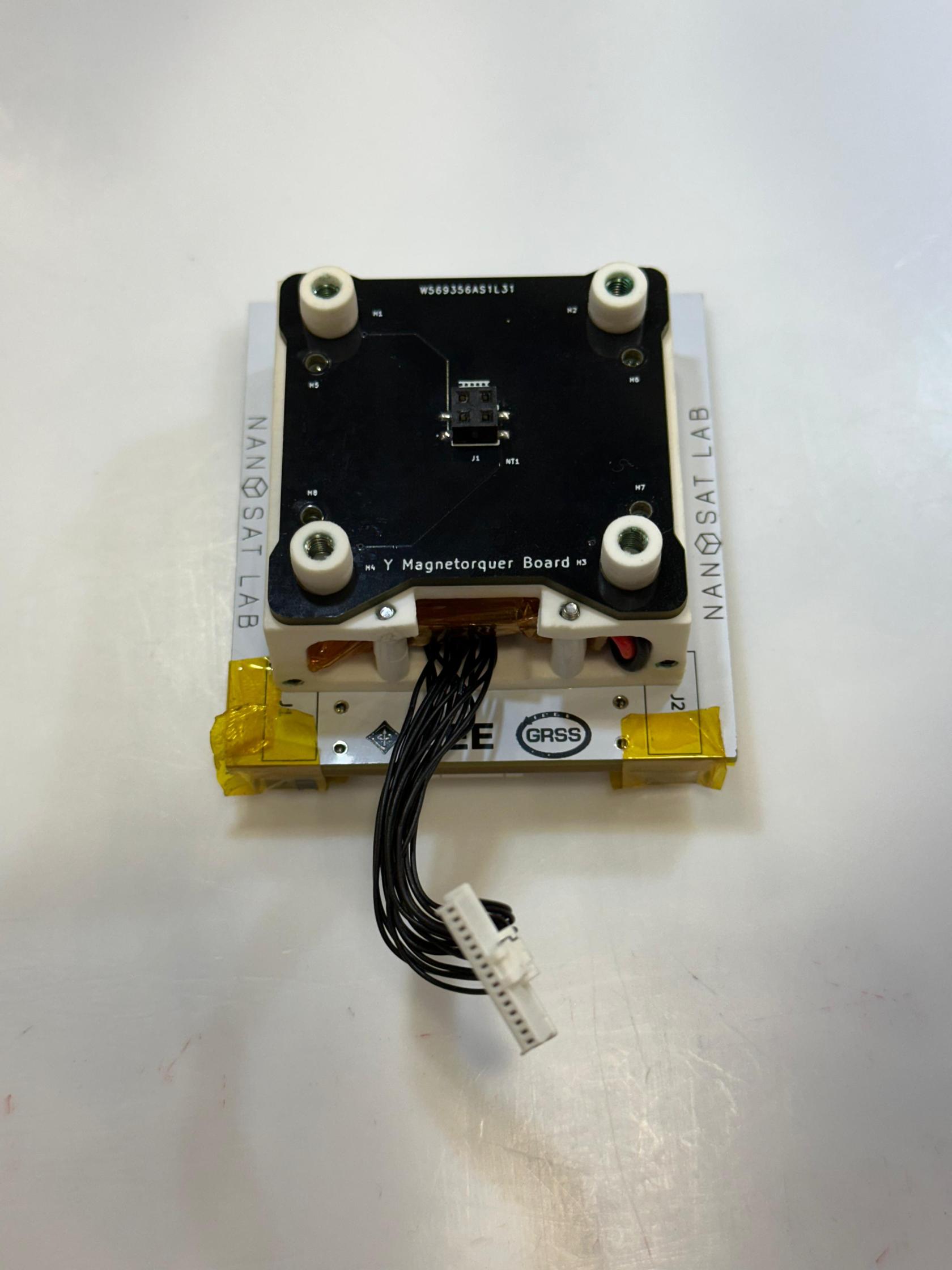](https://wiki.nanosatlab.space/uploads/images/gallery/2025-07/whatsapp-image-2024-11-13-at-17-43-22.jpeg) |
| 42 | Recall step 41 4 x SCREW-03 | Fasten all four SCREW-03 into each of the holes. | Torque | [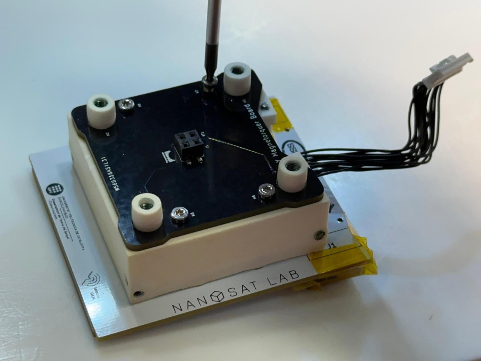](https://wiki.nanosatlab.space/uploads/images/gallery/2025-07/whatsapp-image-2024-11-13-at-17-34-40.jpeg) |
| 50 | 1 x Complete assembled payload | \- For this assembly procedure, no payload is used. Instead, place a generic top PCB. Replace this upper section with the corresponding payload.
\- The payload and the top structure have been installed according to their specific tutorials; refer to them for more information.
Add reference to tutorials. | ||
| 60 | 1 x Complete assembled payload | The top structure works as an interface between the payload and the platform and must match the specifications of the PocketQube. Additionally, the height of the spacers must be appropriate to match the PocketQube height specification. | Depending on the payload, SPACER-02 and top structure will vary.
The top structure, including the payload, must be custom-developed by each team. In our case, we've used a VGA payload as an example.
Especificar a la Wiki aquests requirements. | [](https://wiki.nanosatlab.space/uploads/images/gallery/2025-07/whatsapp-image-2024-11-13-at-15-38-37-1.jpeg) [](https://wiki.nanosatlab.space/uploads/images/gallery/2025-07/whatsapp-image-2024-11-13-at-15-38-37.jpeg) |
| 70 | 1 x OBC-COMMS soldered board 1 x RF cable | Prepare the components. | [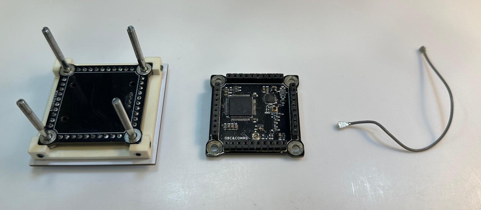](https://wiki.nanosatlab.space/uploads/images/gallery/2025-07/whatsapp-image-2024-11-13-at-15-51-30.jpeg) | |
| 71 | 1 x OBC-COMMS soldered board 1 x RF cable | Using tweezers, connect the head of the RF cable to the connector placed on the board. | The RF cable should exit the PCB passing through the the bottom right aperture as shown in the image, leaving room for SCREW-4 to be added later in the assembly process. | [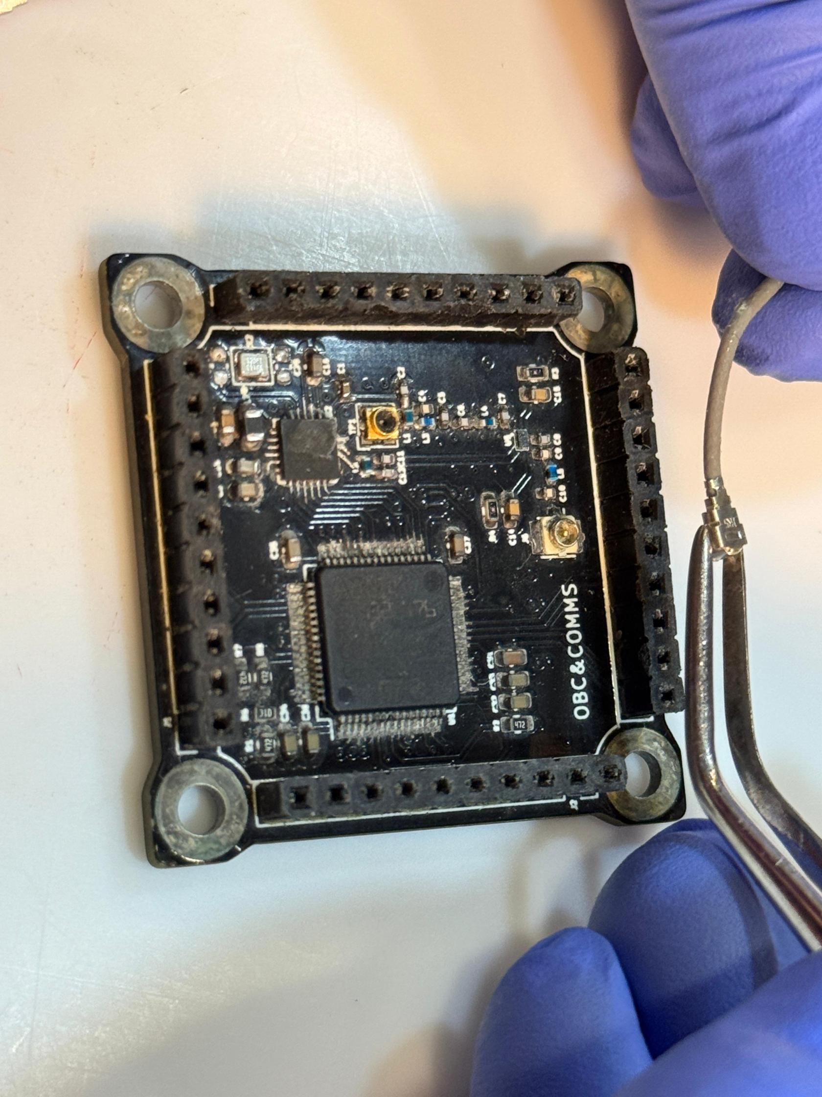](https://wiki.nanosatlab.space/uploads/images/gallery/2025-07/whatsapp-image-2024-11-13-at-15-55-03.jpeg) [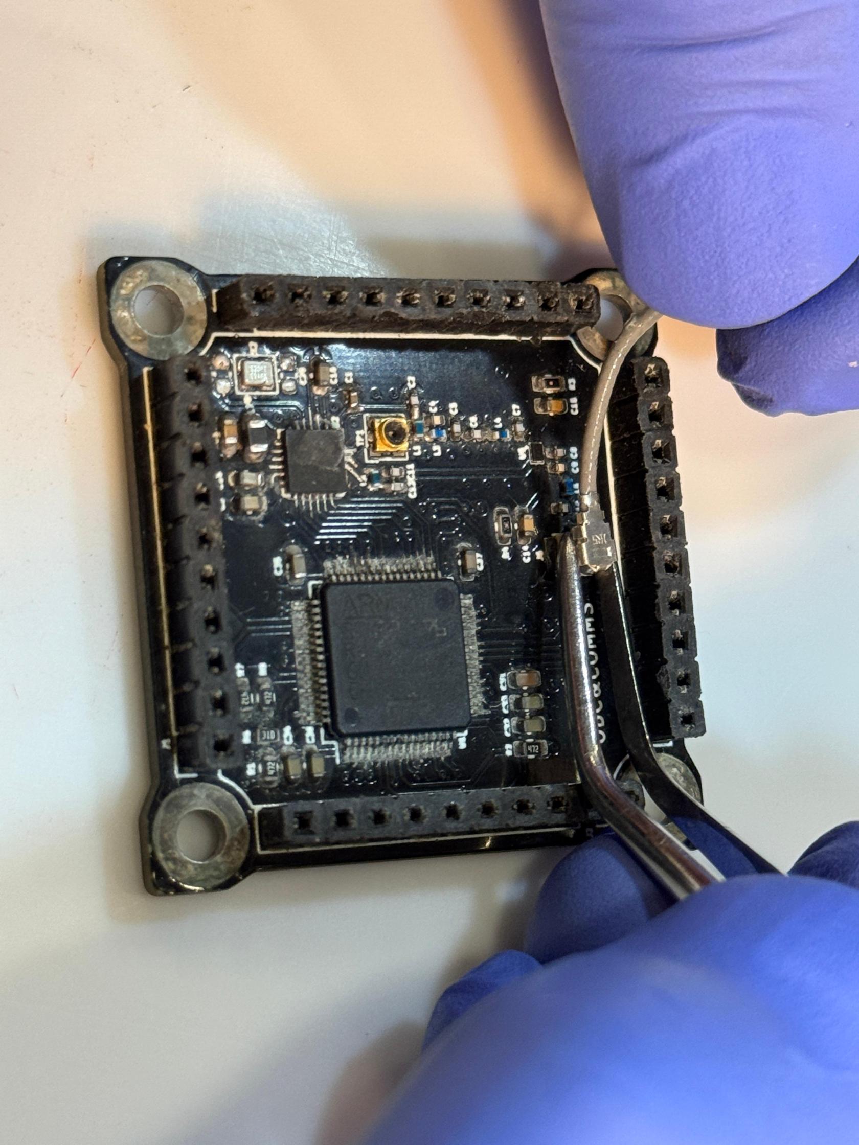](https://wiki.nanosatlab.space/uploads/images/gallery/2025-07/whatsapp-image-2024-11-13-at-15-55-03-1.jpeg) [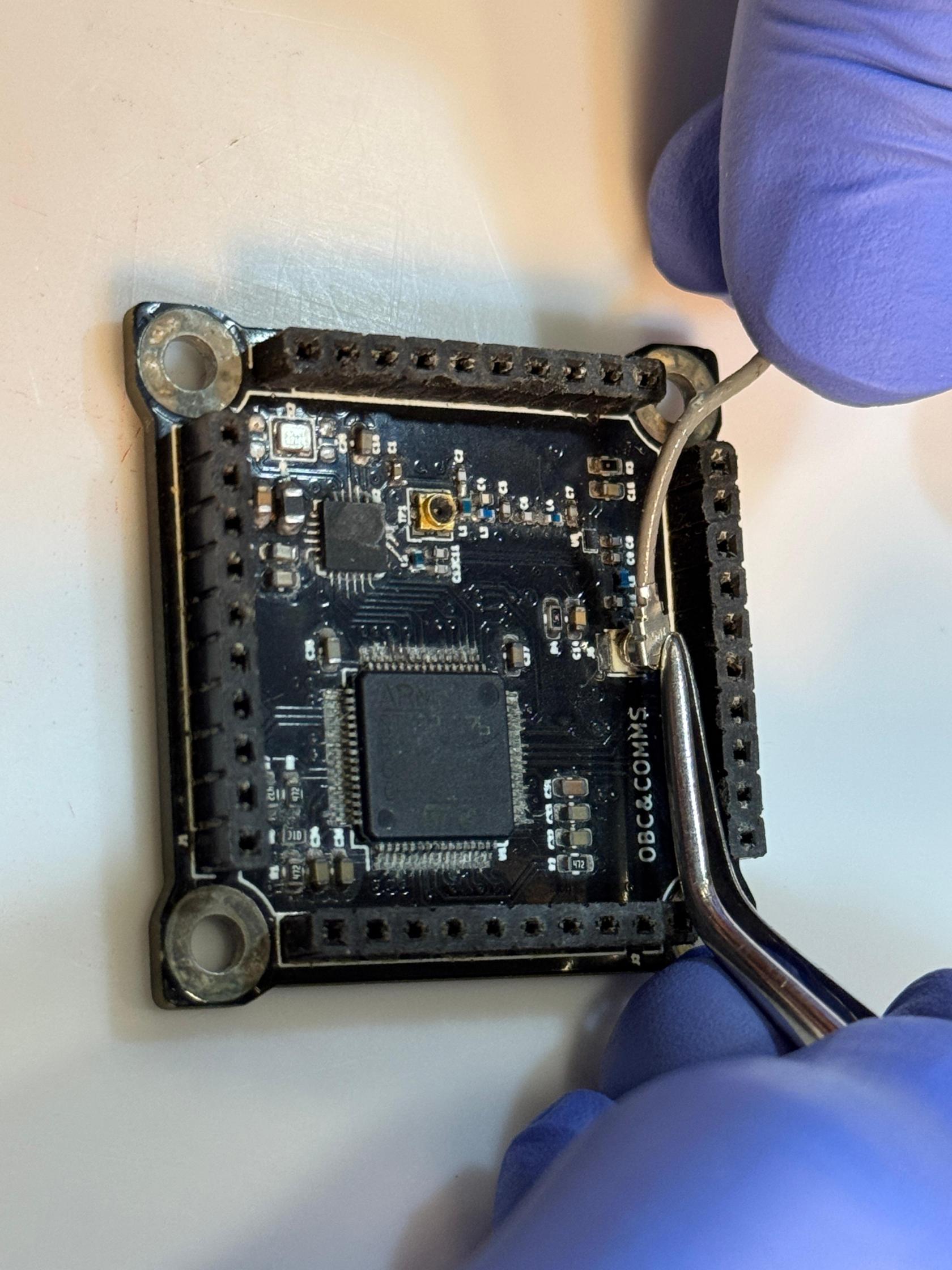](https://wiki.nanosatlab.space/uploads/images/gallery/2025-07/whatsapp-image-2024-11-13-at-15-55-03-2.jpeg) [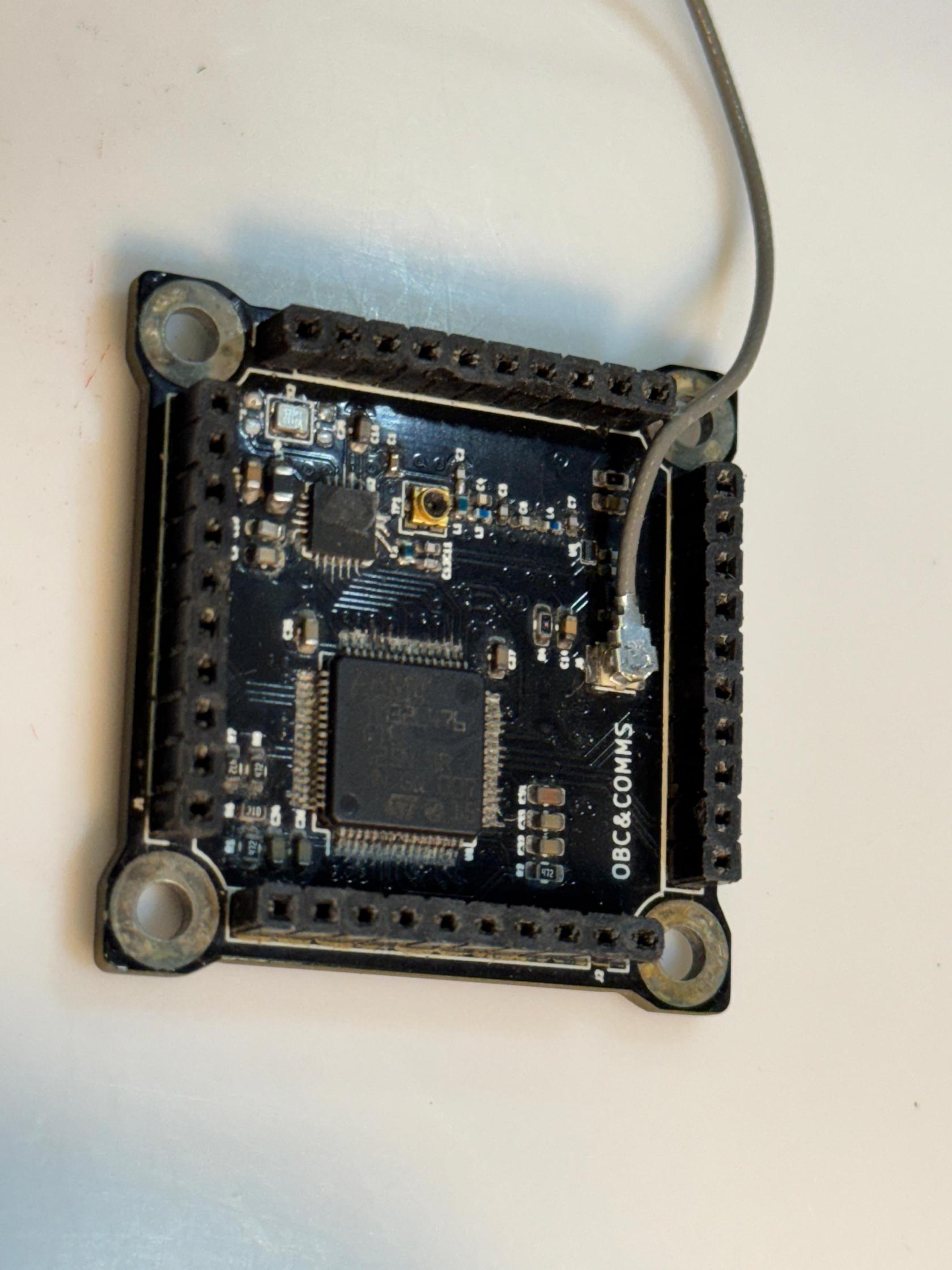](https://wiki.nanosatlab.space/uploads/images/gallery/2025-07/whatsapp-image-2024-11-13-at-15-55-03-3.jpeg) [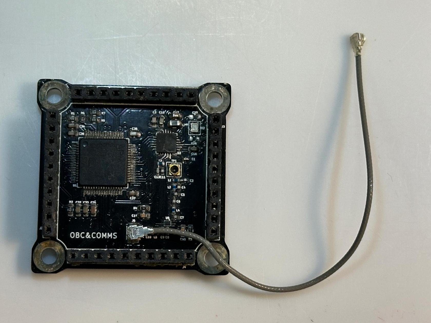](https://wiki.nanosatlab.space/uploads/images/gallery/2025-07/whatsapp-image-2024-11-13-at-16-00-14.jpeg) |
| 80 | 1 x Complete OBC-COMMS board from step 71 1 x Complete ADCS board 1 x Complete EPS board 1 x Complete assembled payload 12 x SPACER-03 12 x SPACER-04 | Prepare the components for assembling the OBC-COMMS, ADCS, and EPS boards. The steps for the assembly of a board will be repeated for each one of the boards. | [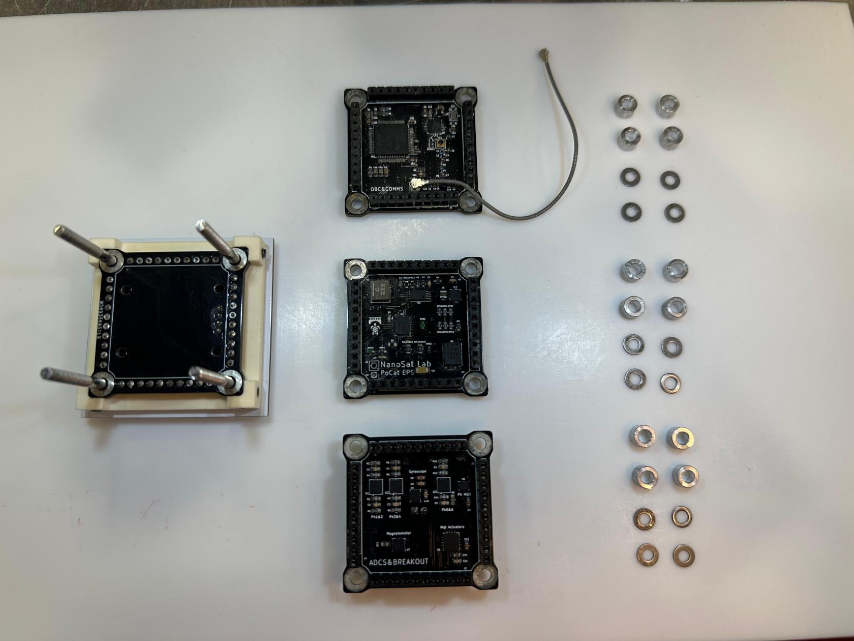](https://wiki.nanosatlab.space/uploads/images/gallery/2025-07/whatsapp-image-2024-11-13-at-16-19-18.jpeg) | |
| 81 | 1 x Complete assembled payload 4 x SPACER-03 | Place one SPACER-03 to each one of the SREW-04 as seen in the image. | [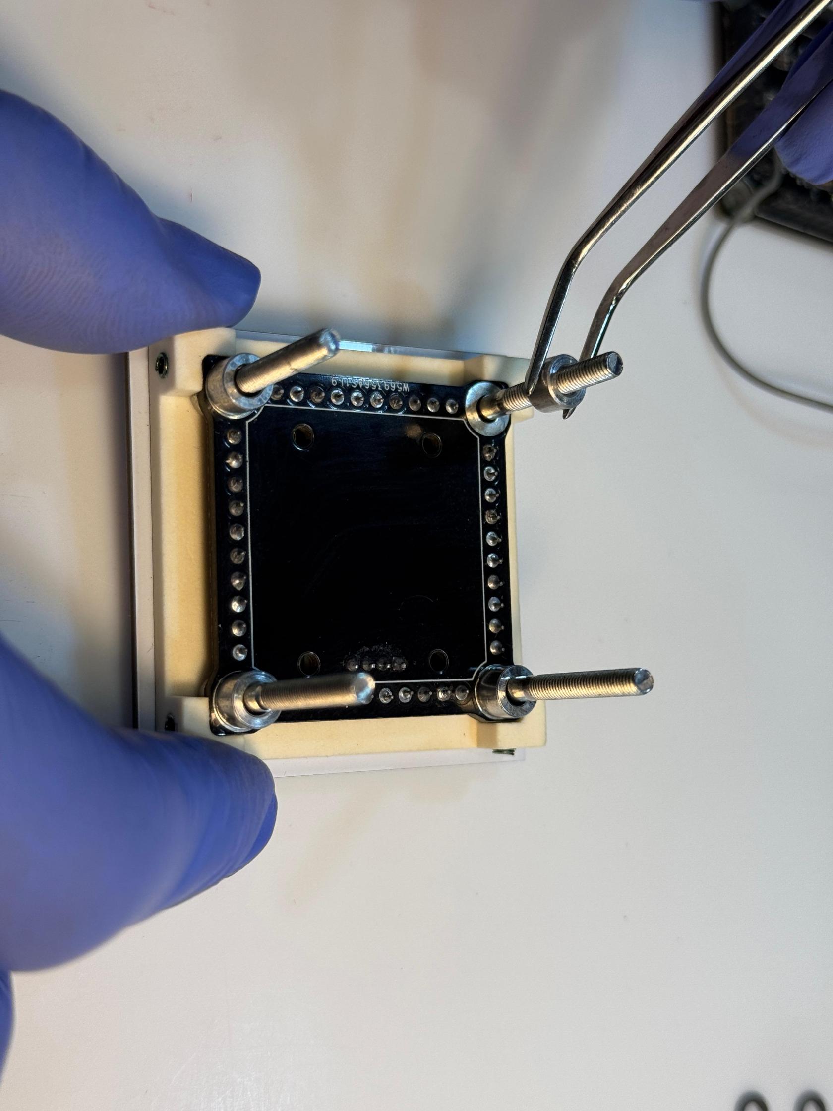](https://wiki.nanosatlab.space/uploads/images/gallery/2025-07/whatsapp-image-2024-11-13-at-16-25-38.jpeg) | |
| 82 | Recall step 71 4 x SPACER-04 | Place one SPACER-04 to each one of the SCREW-04 as seen in the image. | SPACER-04 must be placed on SPACER-03. | [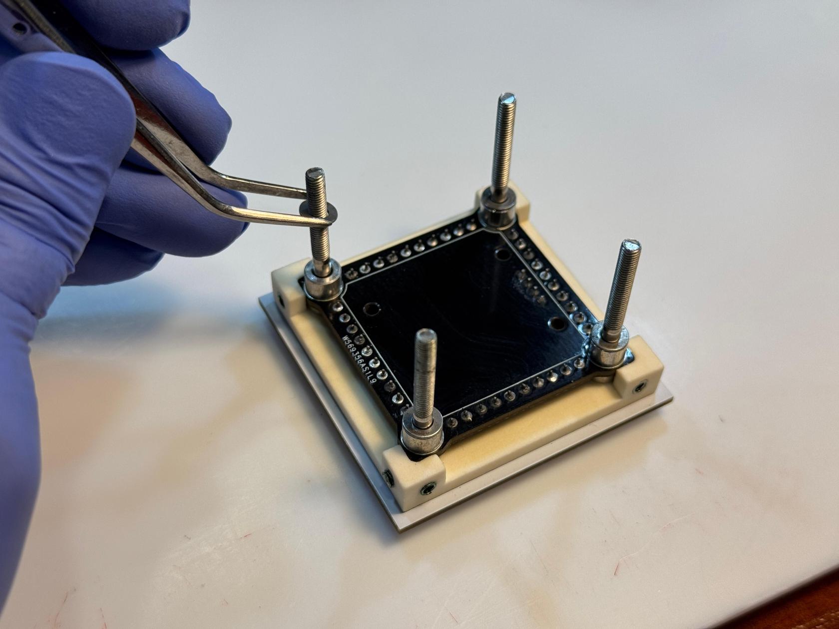](https://wiki.nanosatlab.space/uploads/images/gallery/2025-07/whatsapp-image-2024-11-13-at-16-30-27.jpeg) |
| 83 | Recall step 72 1 x Complete OBC-COMMS board from step 71 | Slide the OBC-COMMS board onto each SCREW-04 from the top structure. Remember that spacers were added in steps 81 and 82. | Carefully ensure the boards are oriented correctly so that the vertical pins align properly. Position the RF cable from the OBC-COMMS board between the SPACER-03 and the vertical connector. | [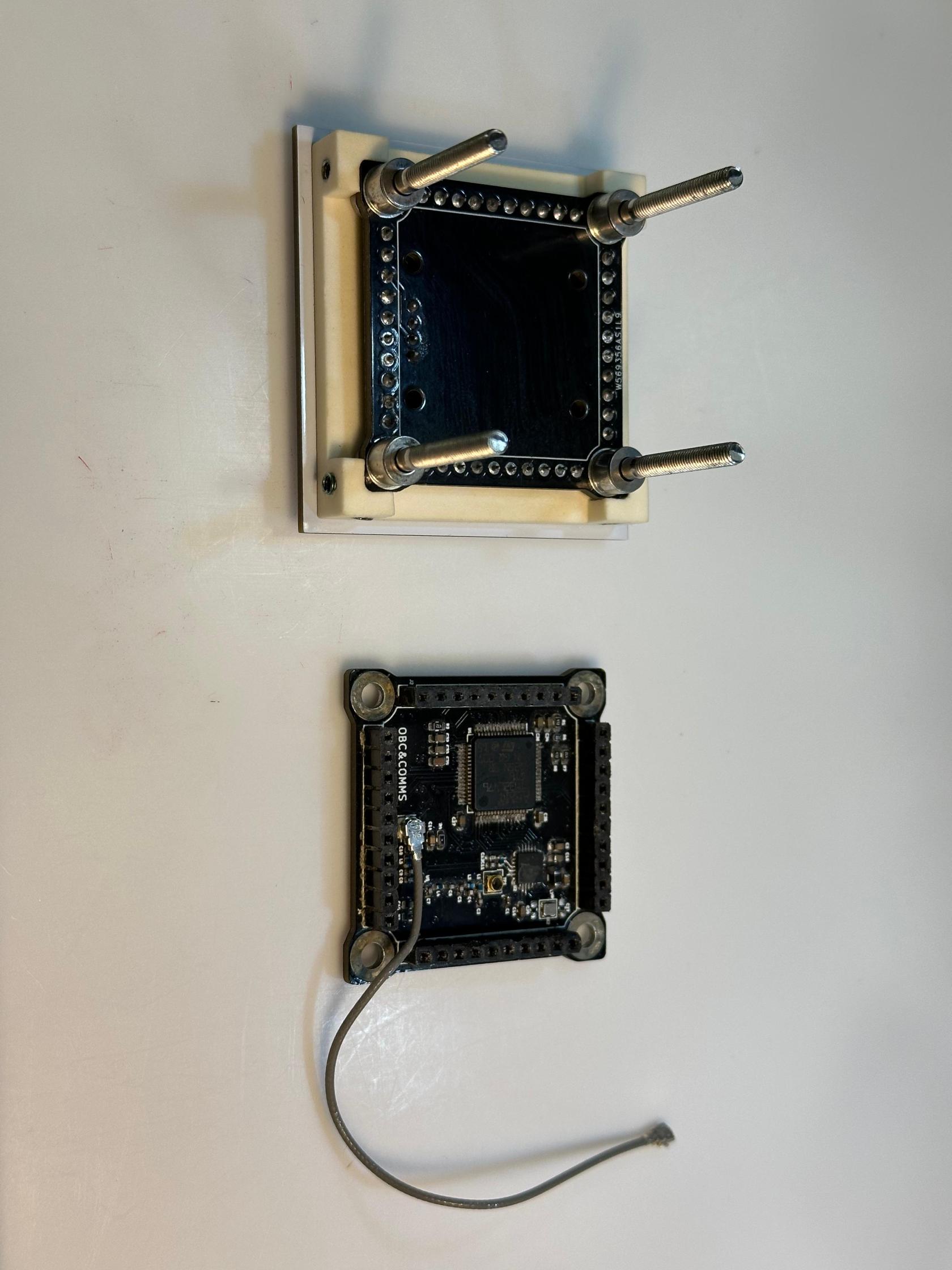](https://wiki.nanosatlab.space/uploads/images/gallery/2025-07/whatsapp-image-2024-11-13-at-16-41-17.jpeg) [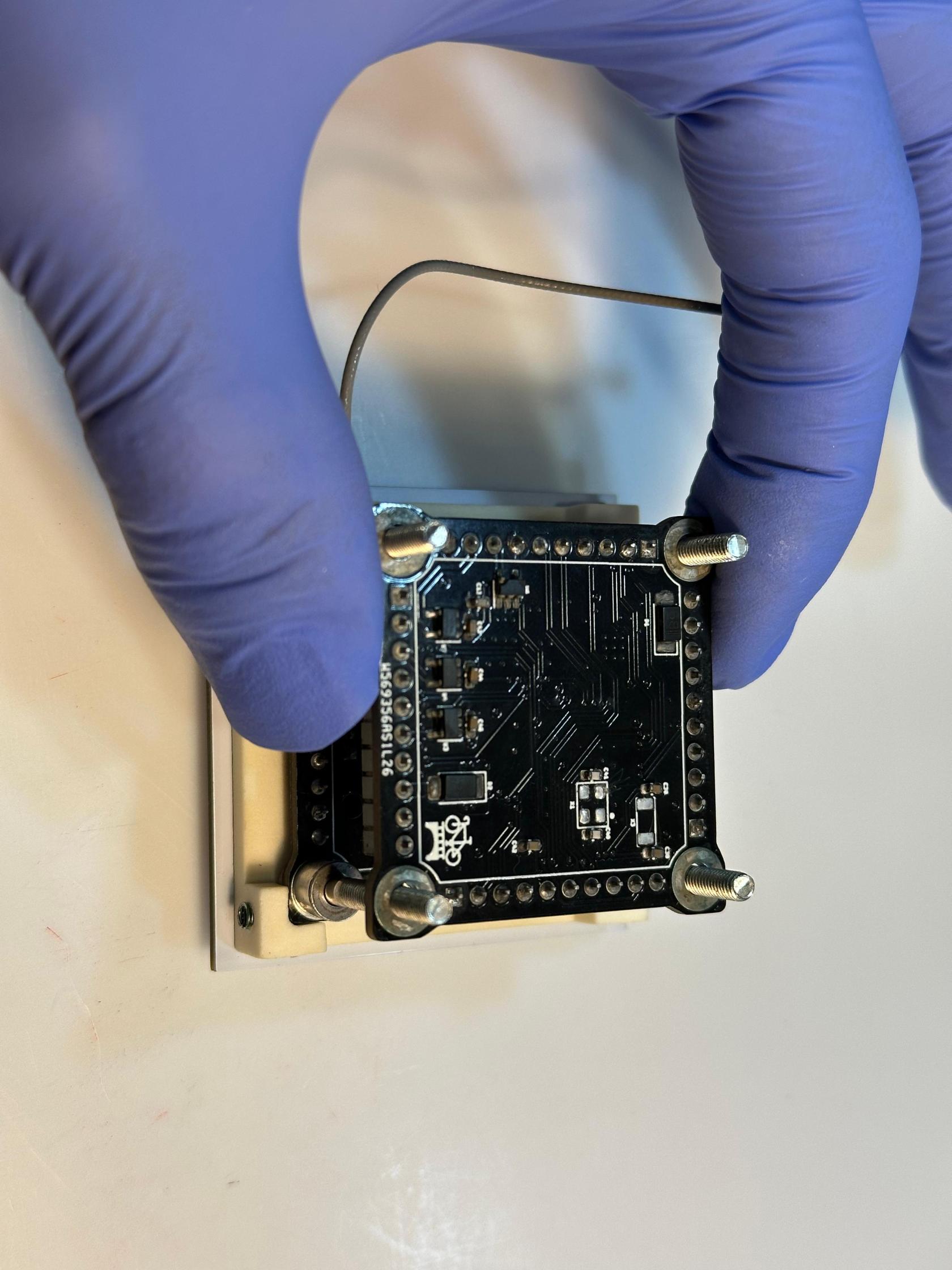](https://wiki.nanosatlab.space/uploads/images/gallery/2025-07/whatsapp-image-2024-11-13-at-16-41-18.jpeg) [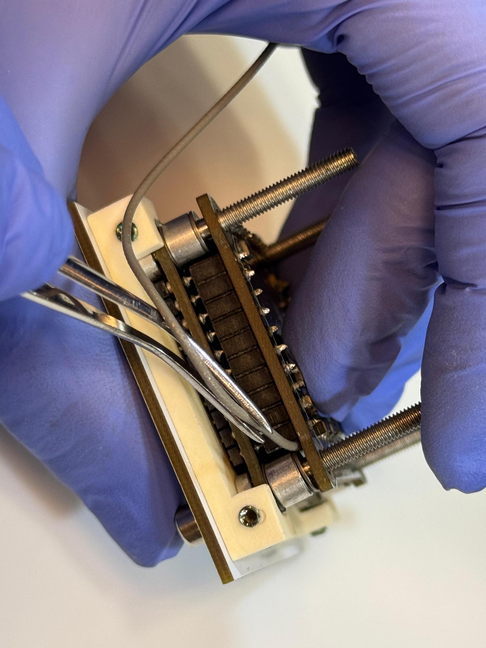](https://wiki.nanosatlab.space/uploads/images/gallery/2025-07/whatsapp-image-2024-11-13-at-16-39-16-1.jpeg) [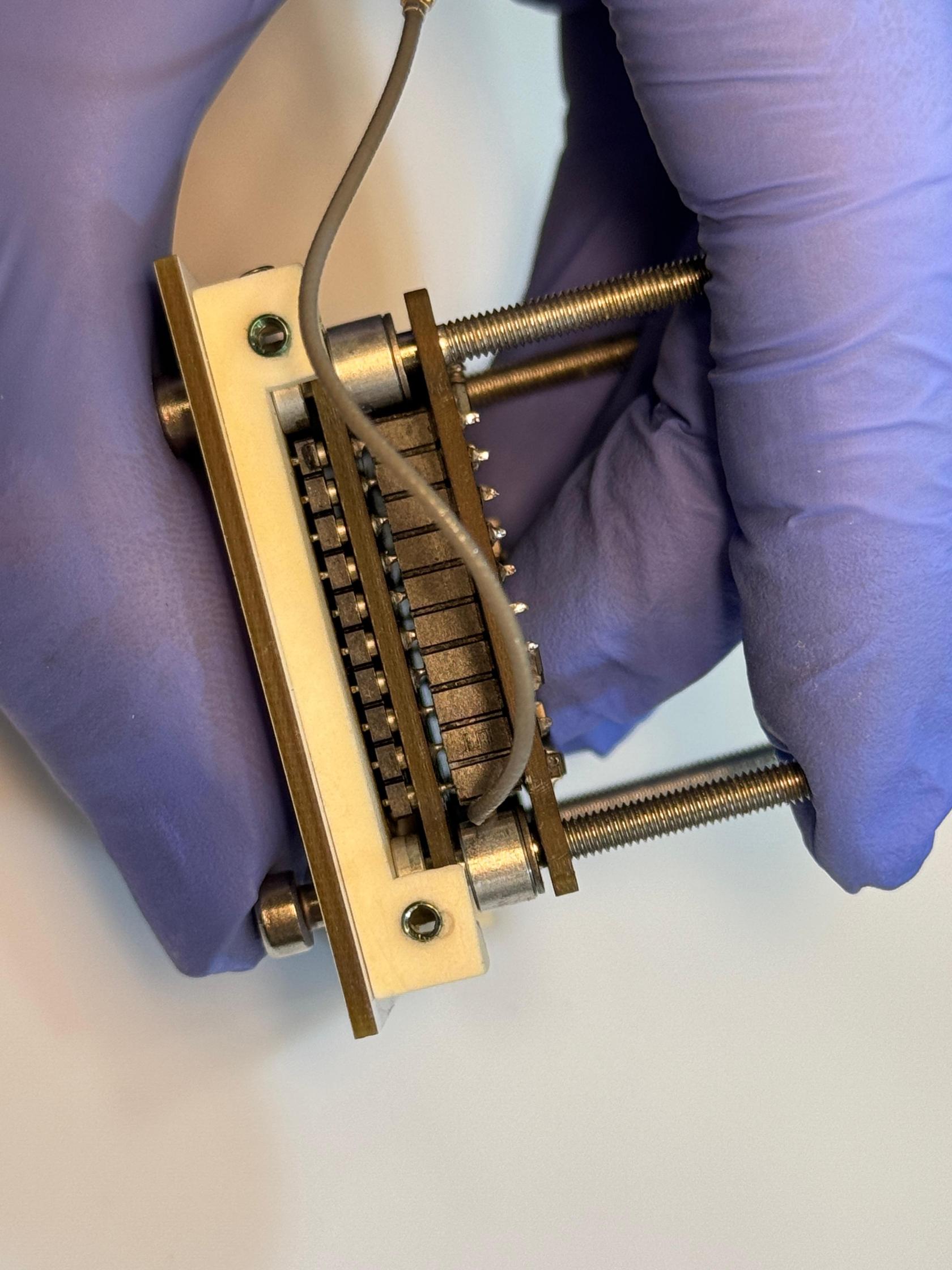](https://wiki.nanosatlab.space/uploads/images/gallery/2025-07/whatsapp-image-2024-11-13-at-16-39-22.jpeg) |
| 84 | Step 83 structure 4 x SPACER-03 4 x SPACER-04 | Prepare the components. | [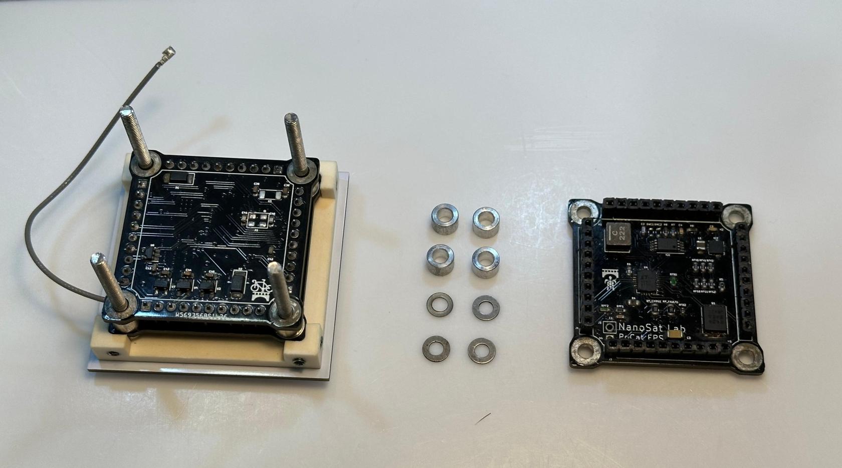](https://wiki.nanosatlab.space/uploads/images/gallery/2025-07/whatsapp-image-2024-11-13-at-17-07-13.jpeg) | |
| 85 | Recall step 83 4 x SPACER-03 | Place one SPACER-03 to each one of the SREW-04 as seen in the image. | The stack shall already contain the assembled OBC-COMMS board. | [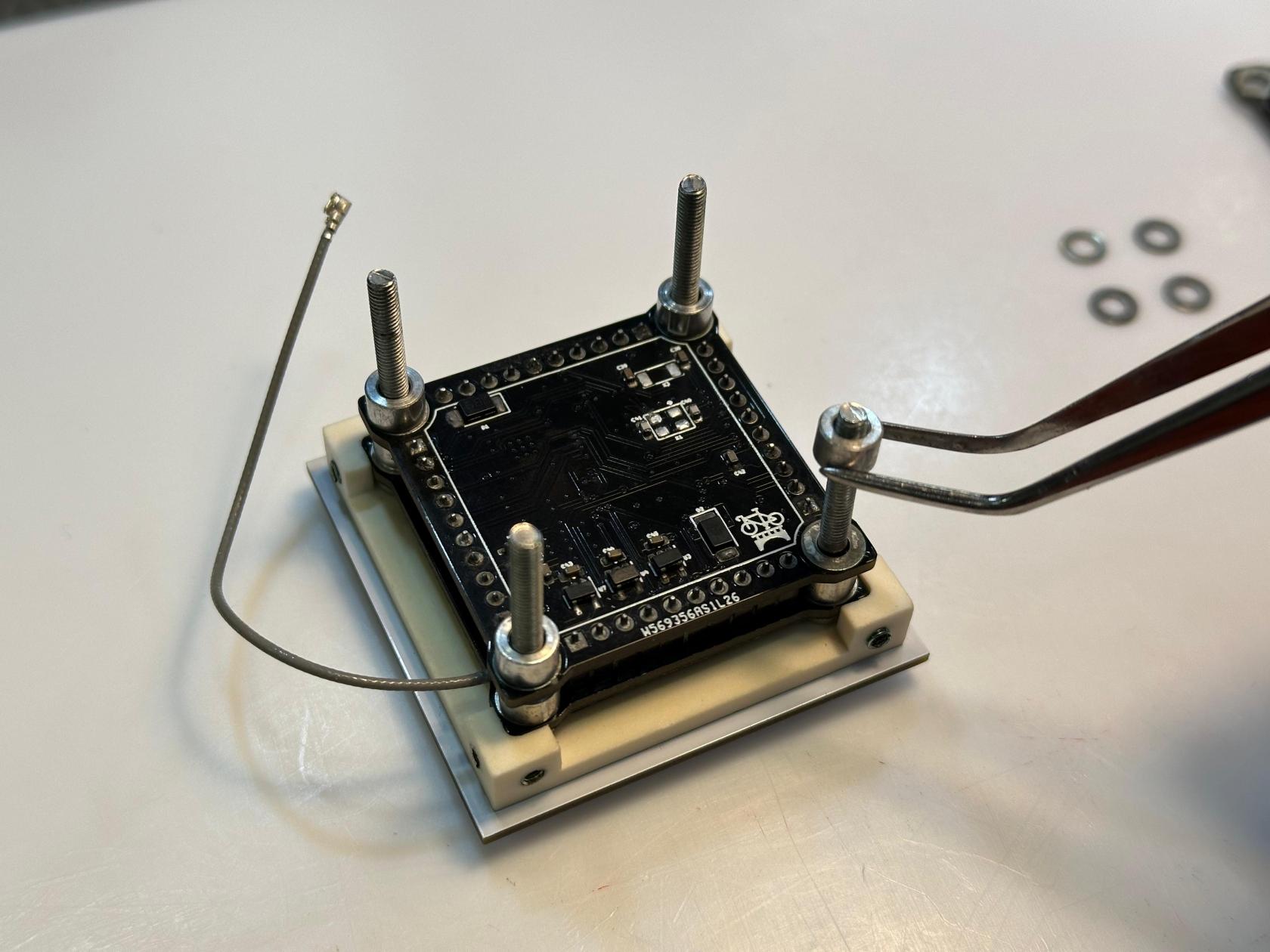](https://wiki.nanosatlab.space/uploads/images/gallery/2025-07/whatsapp-image-2024-11-13-at-17-10-05.jpeg) |
| 86 | Recall step 85 4 x SPACER-04 | Place one SPACER-04 to each one of the SCREW-04 as seen in the image. | SPACER-04 must be placed on SPACER-03. The stack shall already contain the assembled OBC-COMMS board and SPACER-03. | [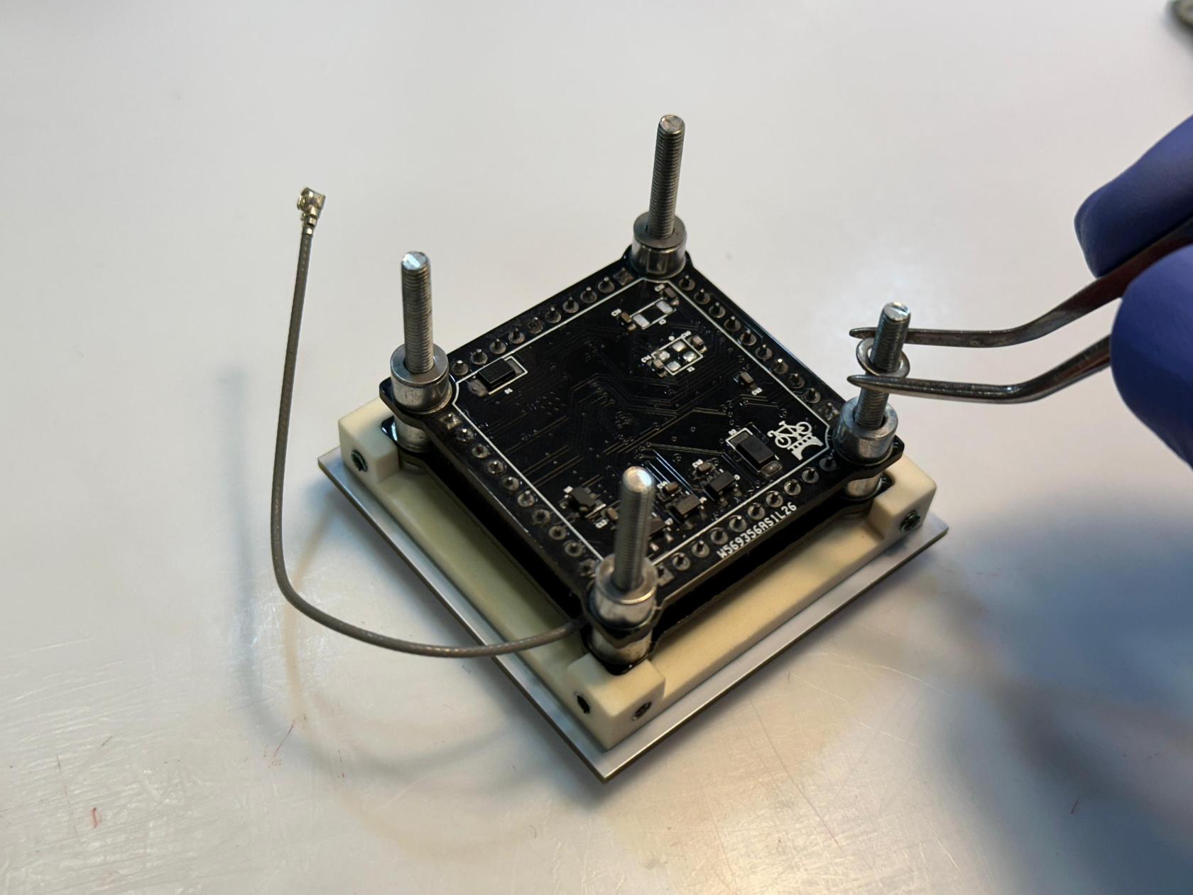](https://wiki.nanosatlab.space/uploads/images/gallery/2025-07/whatsapp-image-2024-11-13-at-17-11-53.jpeg) |
| 87 | Recall step 86 1 x Complete EPS board | Slide the EPS board onto each SCREW-04 from the stack. Remember that spacers were added in steps 85 and 86. | Carefully ensure the boards are oriented correctly so that the vertical pins align properly. | [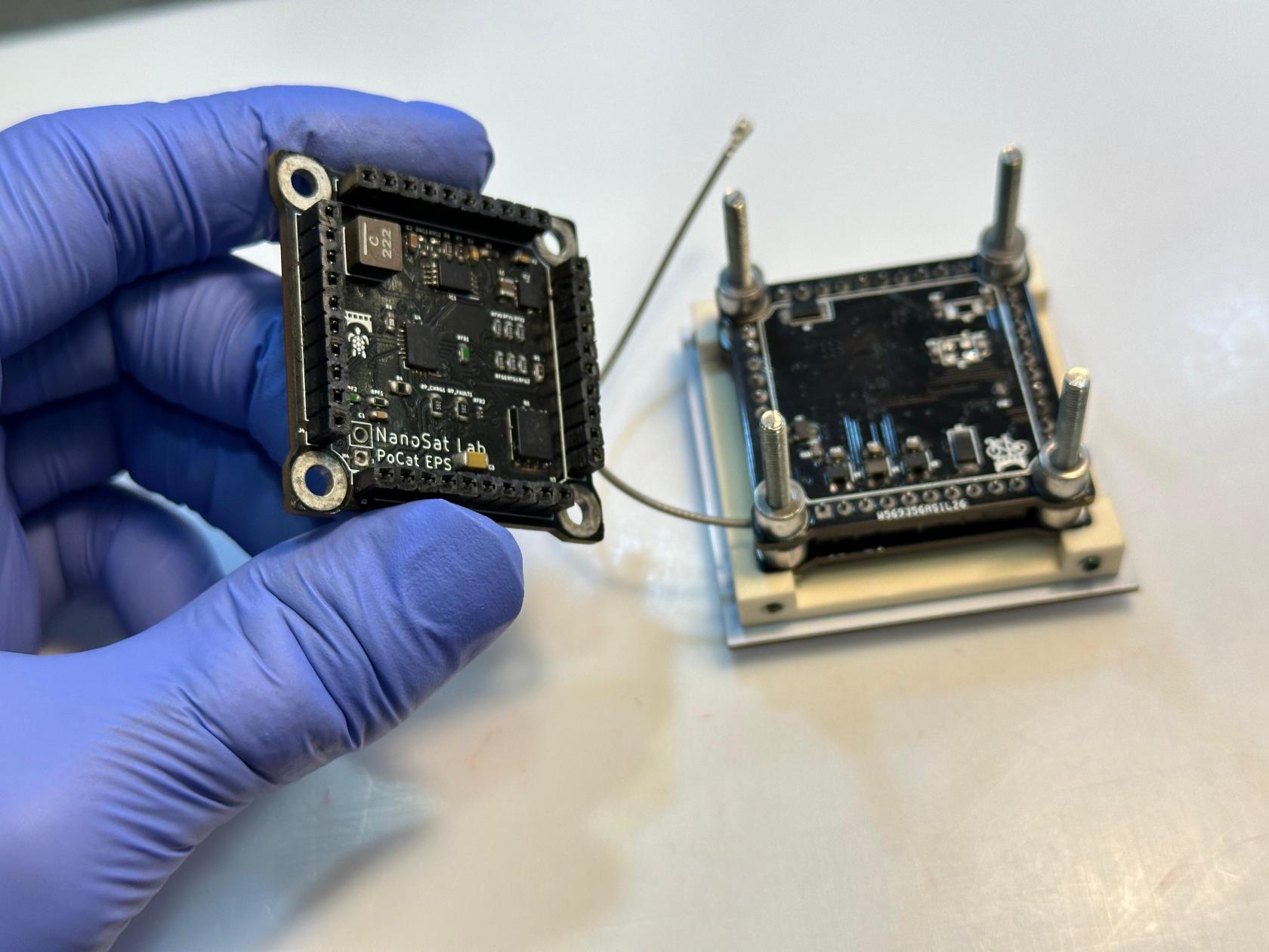](https://wiki.nanosatlab.space/uploads/images/gallery/2025-07/whatsapp-image-2024-11-13-at-17-13-29.jpeg) [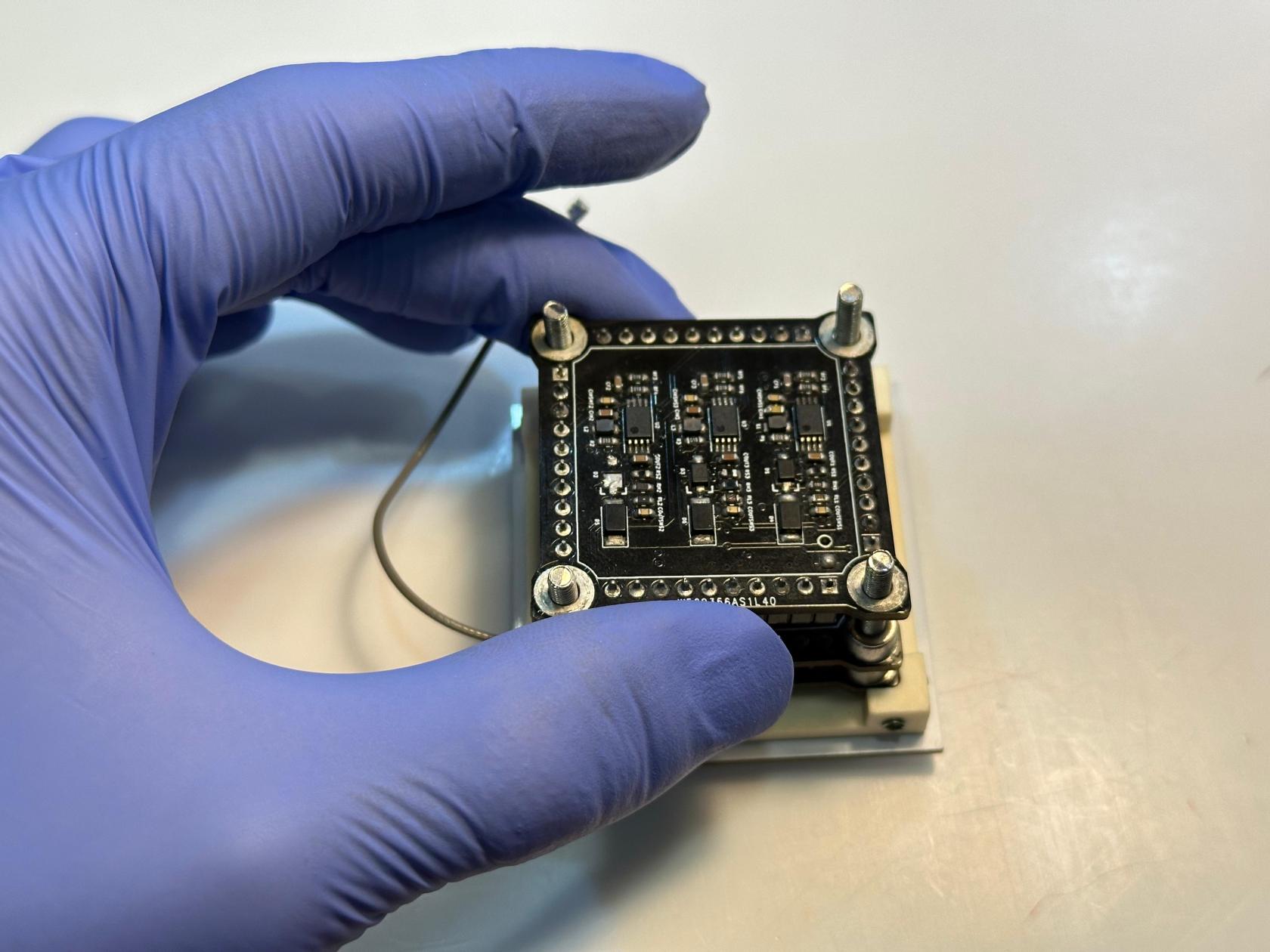](https://wiki.nanosatlab.space/uploads/images/gallery/2025-07/whatsapp-image-2024-11-13-at-17-13-30.jpeg) |
| 88 | Step 87 structure 4 x SPACER-03 4 x SPACER-04 | Prepare the components. | [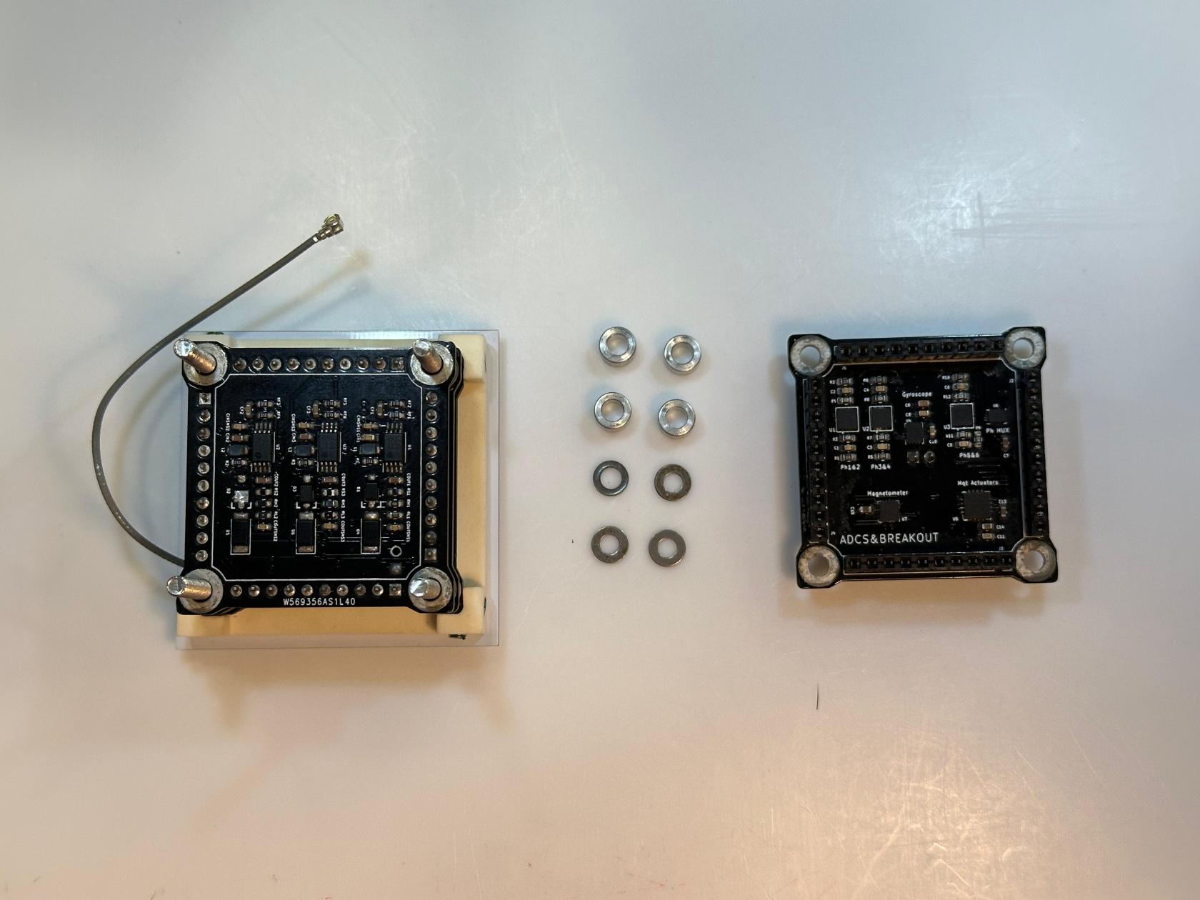](https://wiki.nanosatlab.space/uploads/images/gallery/2025-07/whatsapp-image-2024-11-13-at-17-17-37.jpeg) | |
| 89 | Recall step 87 4 x SPACER-03 | Place one SPACER-03 to each one of the SREW-04 as seen in the image. | The stack shall already contain the assembled OBC-COMMS and EPS boards. | [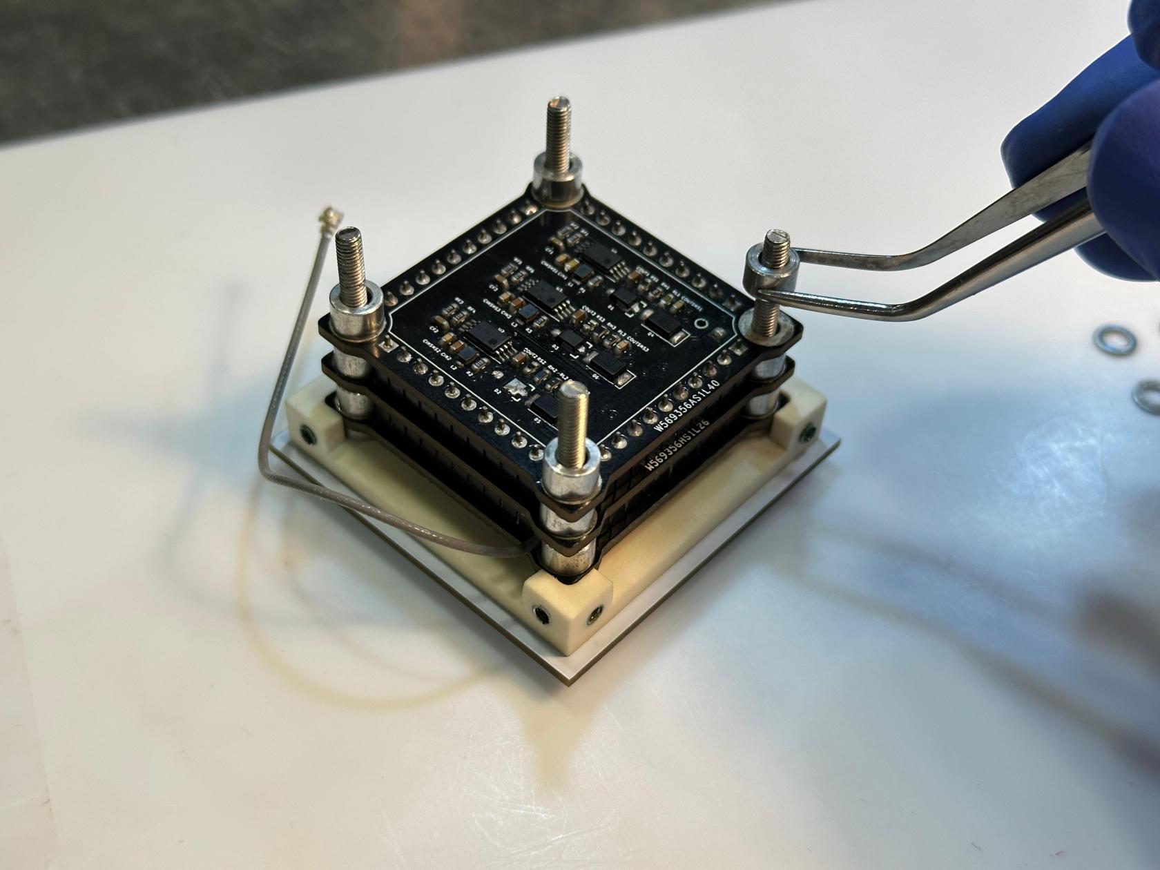](https://wiki.nanosatlab.space/uploads/images/gallery/2025-07/whatsapp-image-2024-11-13-at-17-20-18.jpeg) |
| 810 | Recall step 89 4 x SPACER-04 | Place one SPACER-04 to each one of the SCREW-04 as seen in the image. | SPACER-04 must be placed on SPACER-03. The stack shall already contain the assembled OBC-COMMS and EPS boards and SPACER-03. | [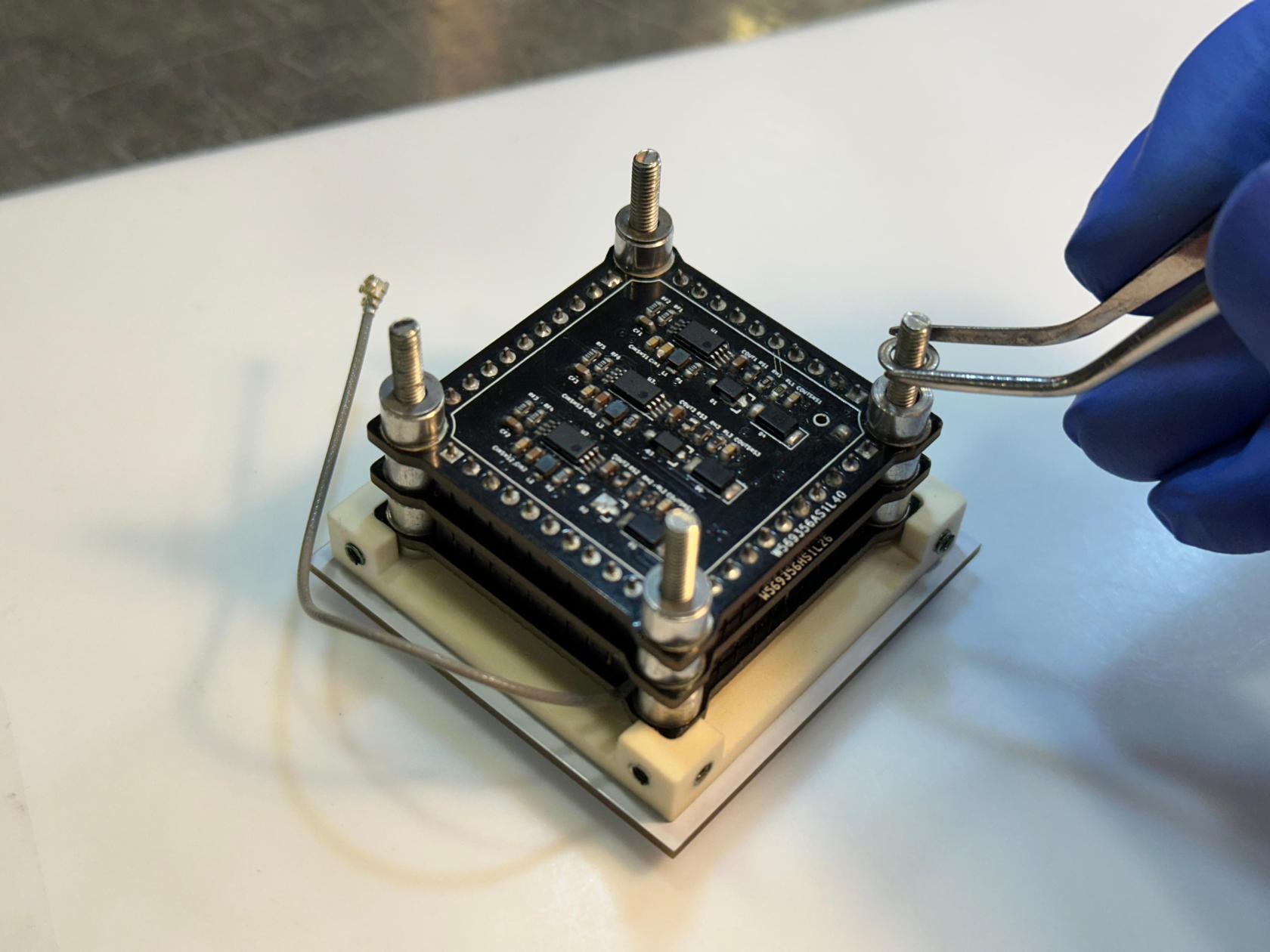](https://wiki.nanosatlab.space/uploads/images/gallery/2025-07/Mi5whatsapp-image-2024-11-13-at-17-20-18.jpeg) |
| 811 | Recall step 810 1 x Complete ACDS board | Slide the ADCS board onto each SCREW-04 from the stack. Remember that spacers were added in steps 89 and 810. | Carefully ensure the boards are oriented correctly so that the vertical pins align properly. | [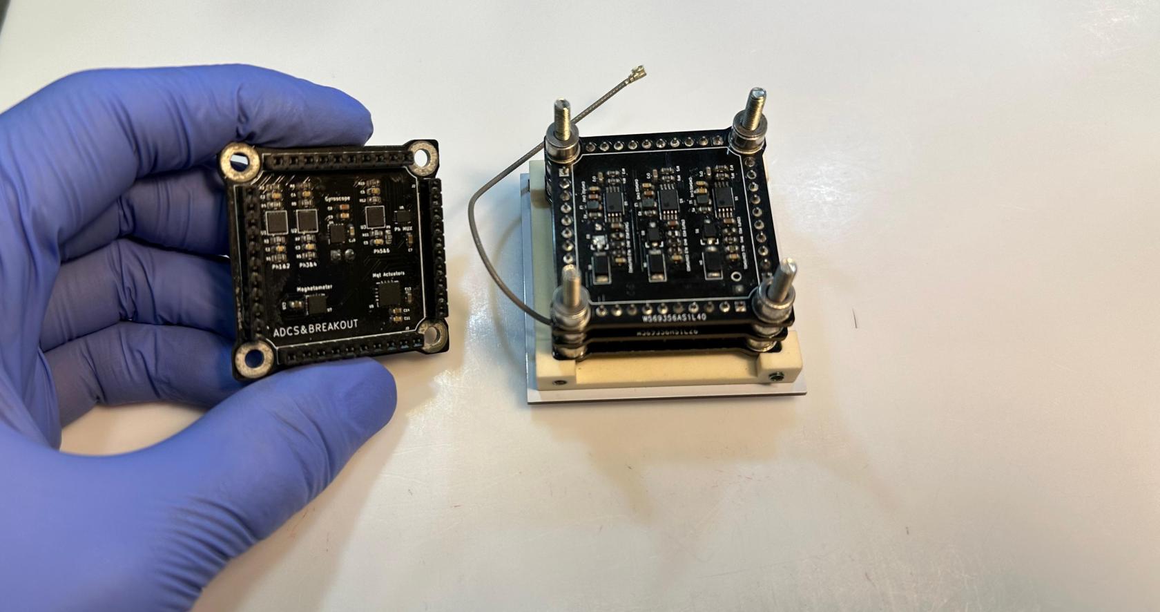](https://wiki.nanosatlab.space/uploads/images/gallery/2025-07/whatsapp-image-2024-11-13-at-17-21-25.jpeg) [](https://wiki.nanosatlab.space/uploads/images/gallery/2025-07/whatsapp-image-2024-11-13-at-17-21-26.jpeg) |
| 90 | 1 x Full stack from step 811 4 x 10xPicoClasp-PicoBlade flat-wire | Connect each flat-wire to the four PicoClasp headers on the ADCS board as shown in the image. | [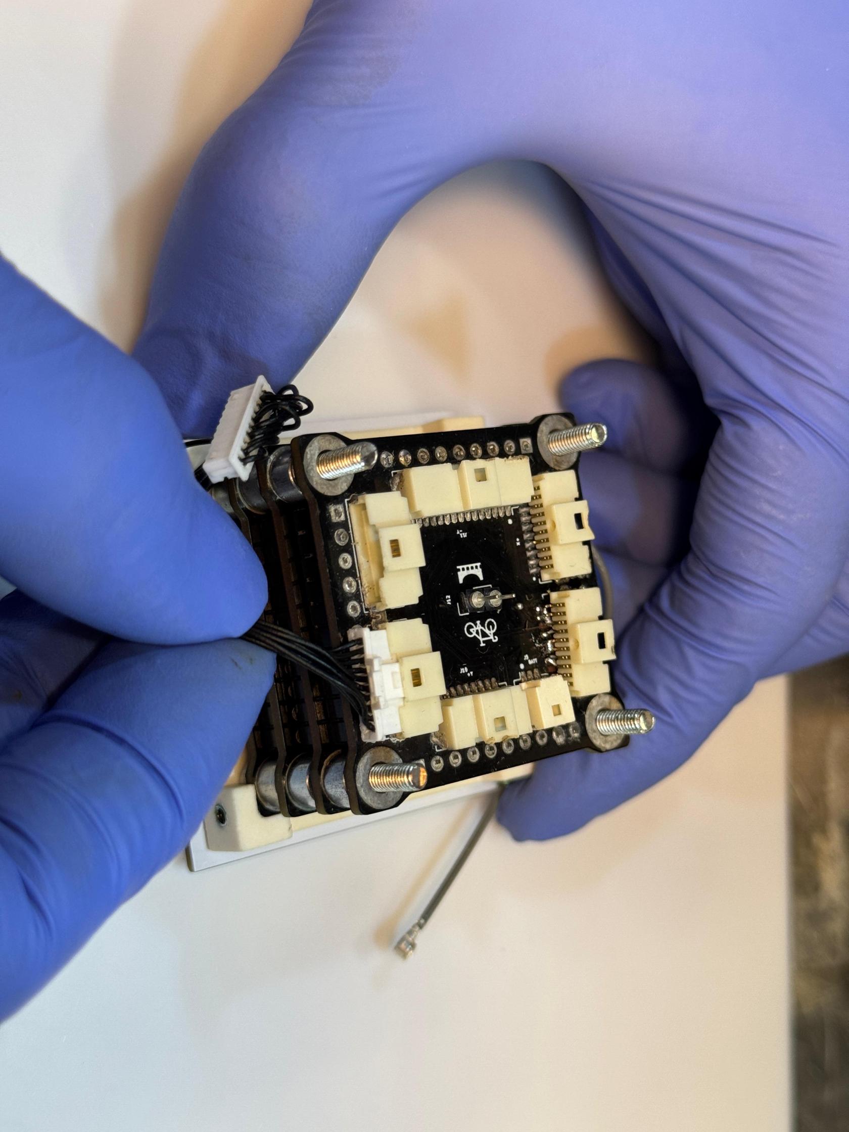](https://wiki.nanosatlab.space/uploads/images/gallery/2025-07/whatsapp-image-2024-11-13-at-18-04-16.jpeg) [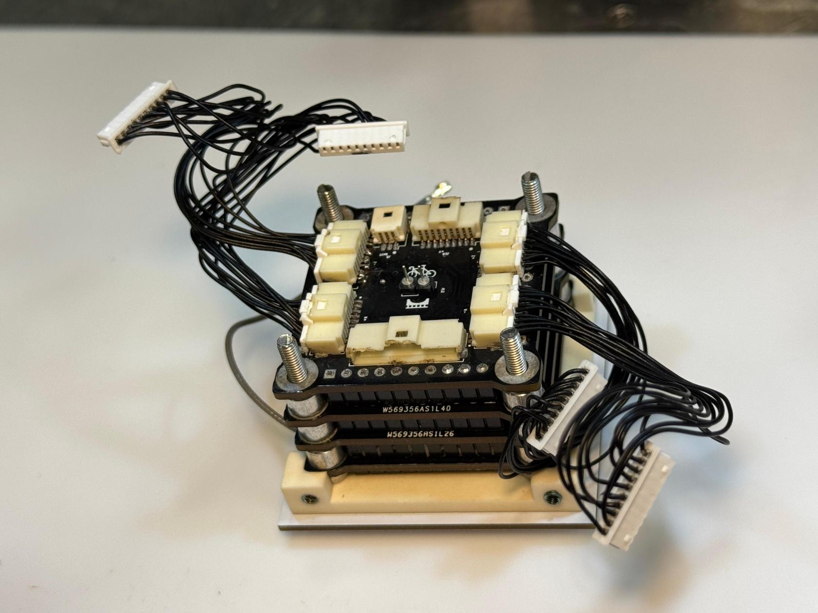](https://wiki.nanosatlab.space/uploads/images/gallery/2025-07/whatsapp-image-2024-11-13-at-18-04-16-2.jpeg) | |
| 100 | 1 x Full stack from step 90 1 x Assembled bottom structure step 42 | Prepare the components. | [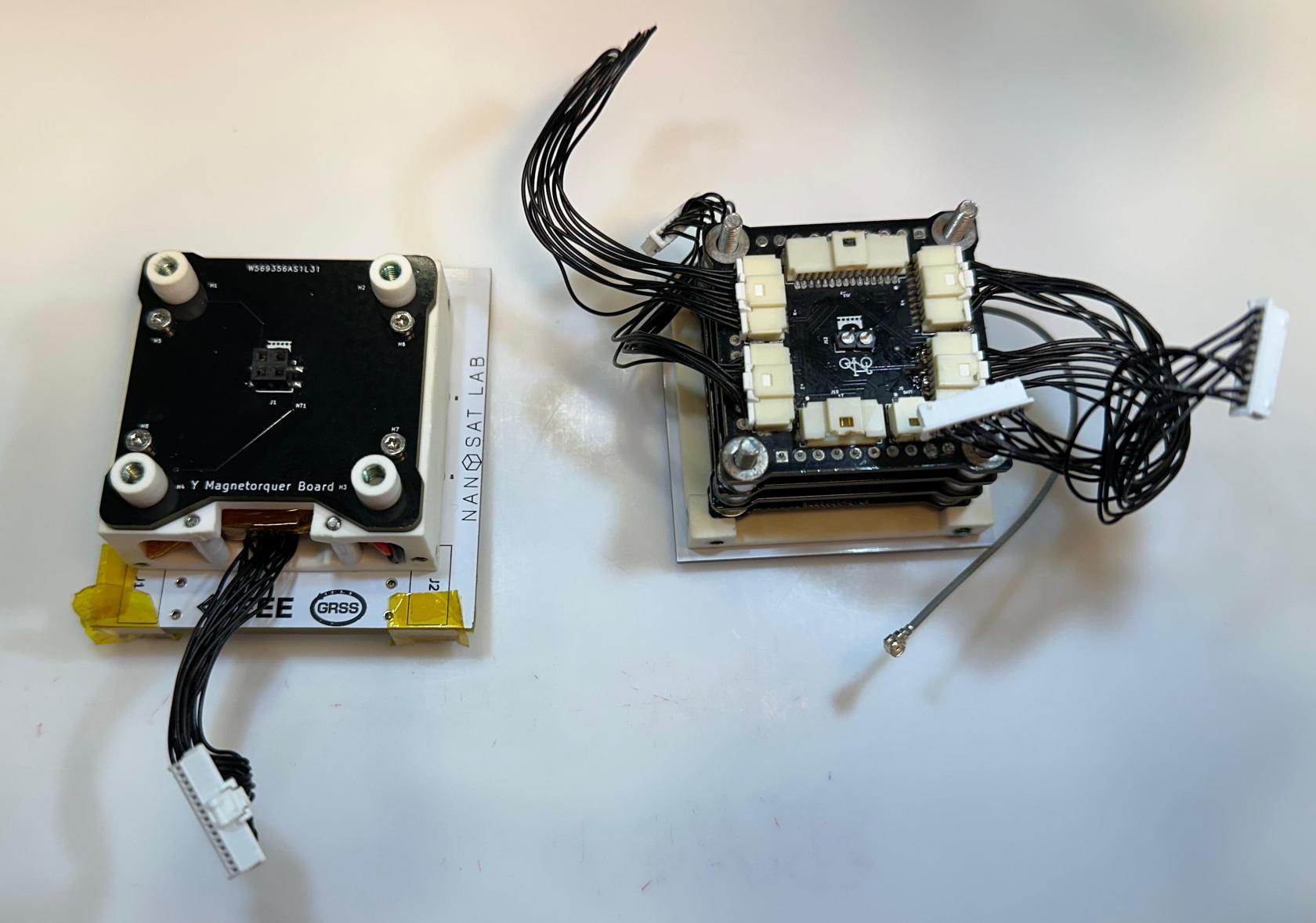](https://wiki.nanosatlab.space/uploads/images/gallery/2025-07/whatsapp-image-2024-11-13-at-18-11-14.jpeg) | |
| 101 | 1 x Full stack from step 90 | Rotate the top structure stack so that the payload is oriented upward. | Using your fingers, apply pressure to all four SCREW-04 to keep them in place while rotating, preventing them from falling. Once the structure is rotated, carefully maintain pressure on the ADCS board to ensure the boards stay in position and doesn't fall. | |
| 102 | 1 x Full stack from step 90 1 x Assembled bottom structure step 42 | Position the top structure on top of the assembled bottom structure. Make sure all four SCREW-04 are correctly positioned. | Carefully verify that both structures are properly aligned. The 15-pin flat-wire should be positioned to face the 15-pin connector coming out the battery aperture. | [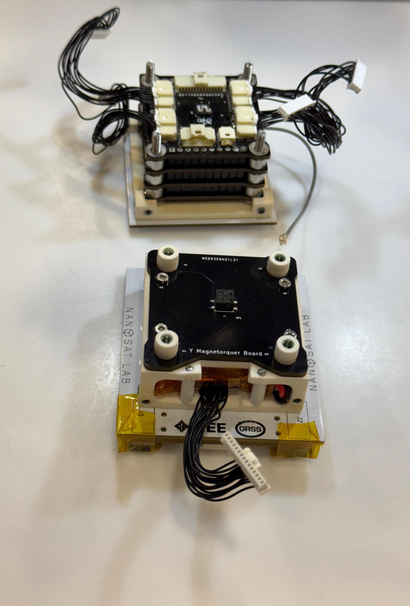](https://wiki.nanosatlab.space/uploads/images/gallery/2025-07/whatsapp-image-2024-11-13-at-20-04-03.jpeg) [](https://wiki.nanosatlab.space/uploads/images/gallery/2025-07/whatsapp-image-2024-11-13-at-20-04-04-1.jpeg) [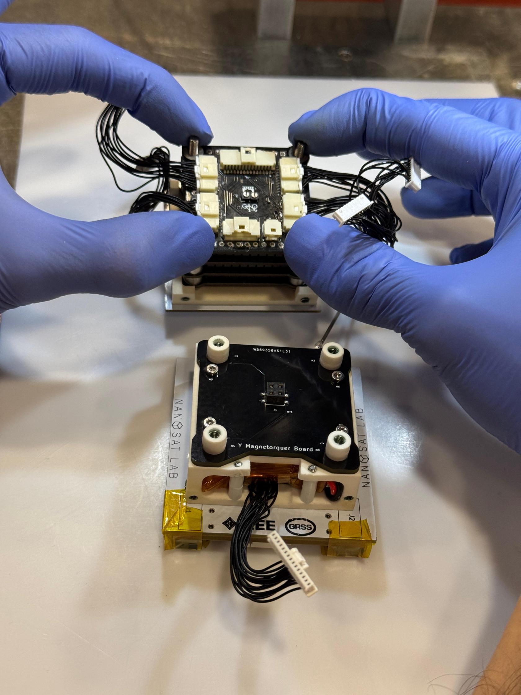](https://wiki.nanosatlab.space/uploads/images/gallery/2025-07/whatsapp-image-2024-11-13-at-20-04-04-2.jpeg) [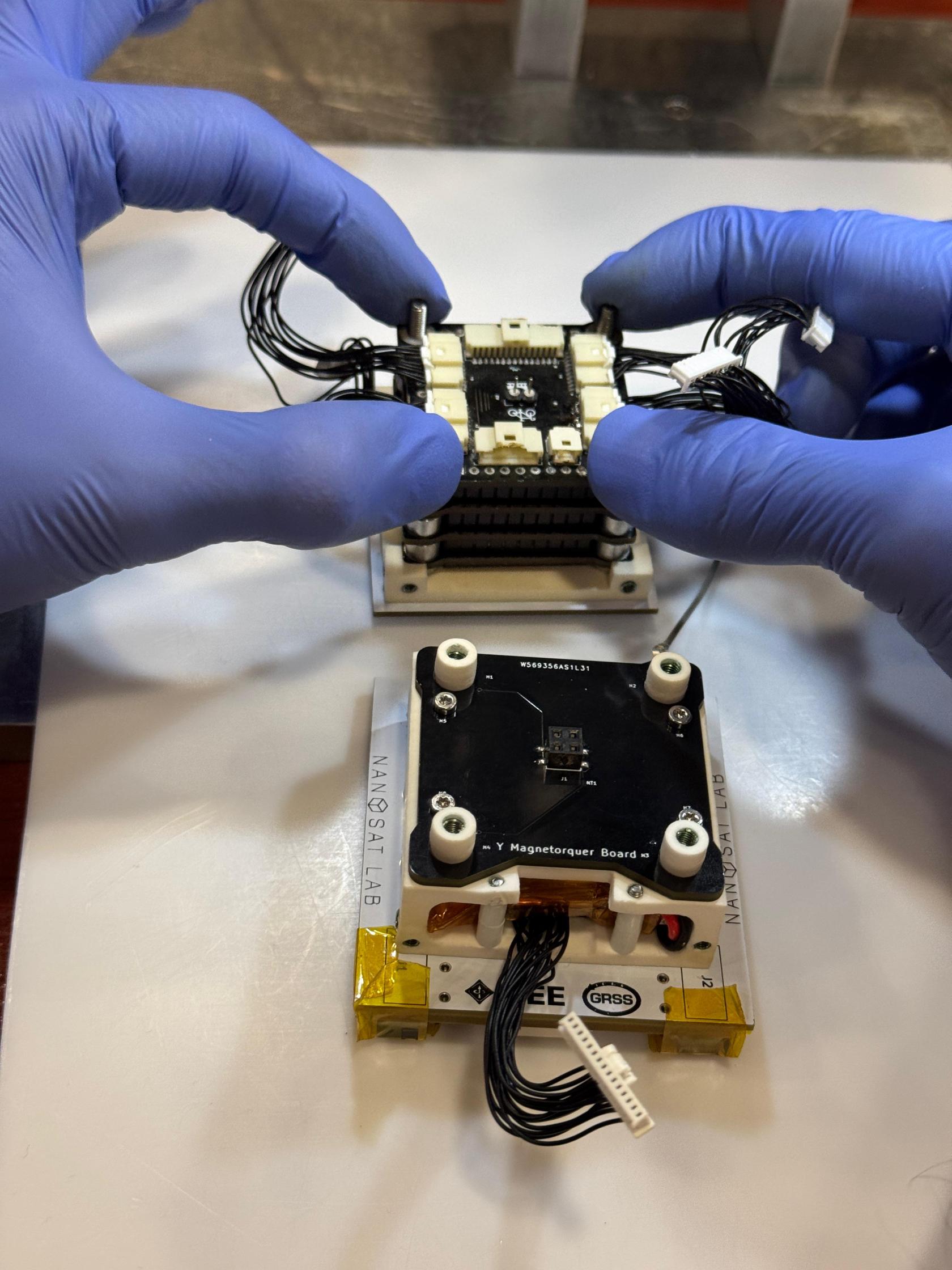](https://wiki.nanosatlab.space/uploads/images/gallery/2025-07/whatsapp-image-2024-11-13-at-20-04-04.jpeg) [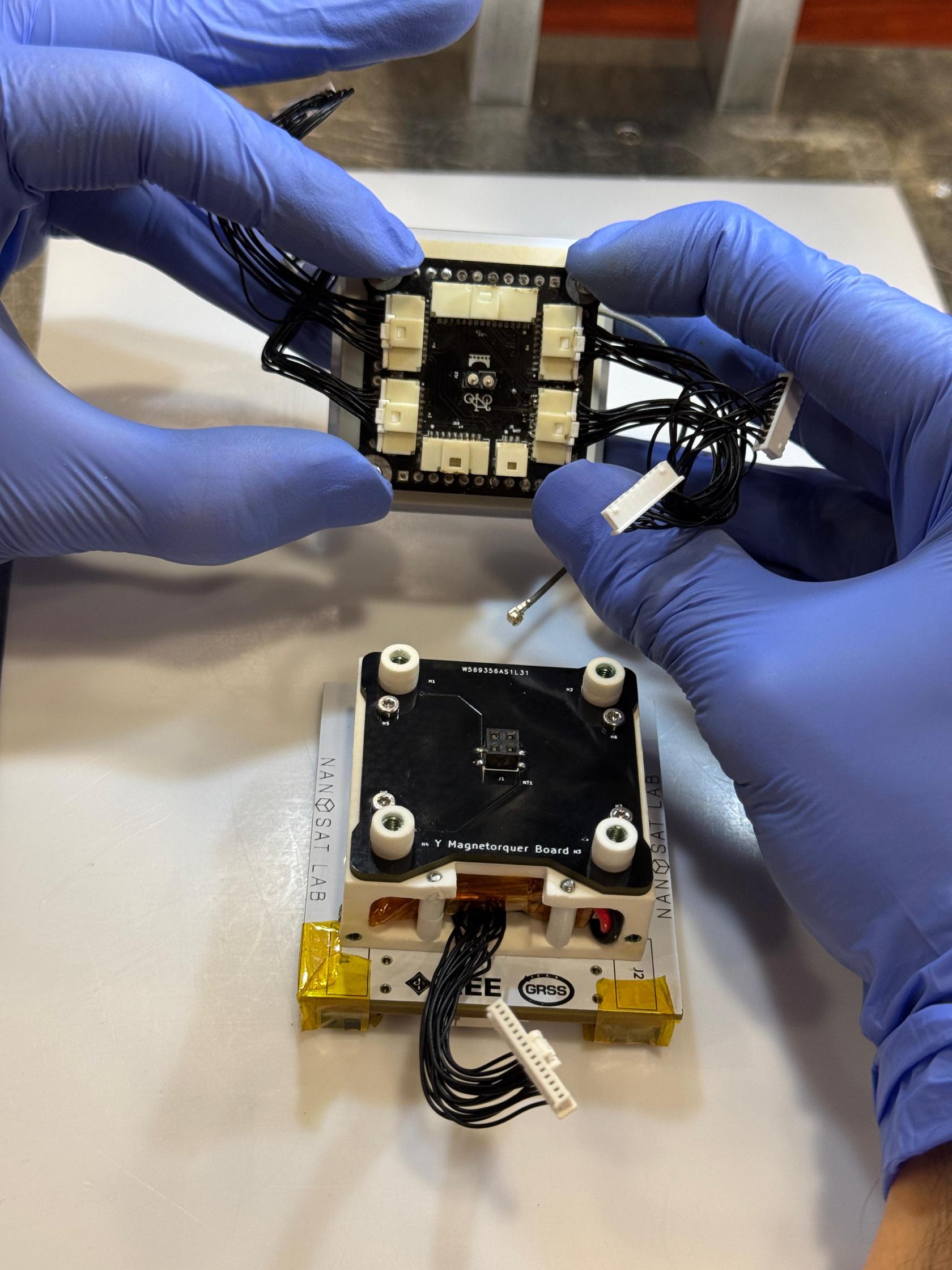](https://wiki.nanosatlab.space/uploads/images/gallery/2025-07/whatsapp-image-2024-11-13-at-20-04-05.jpeg) [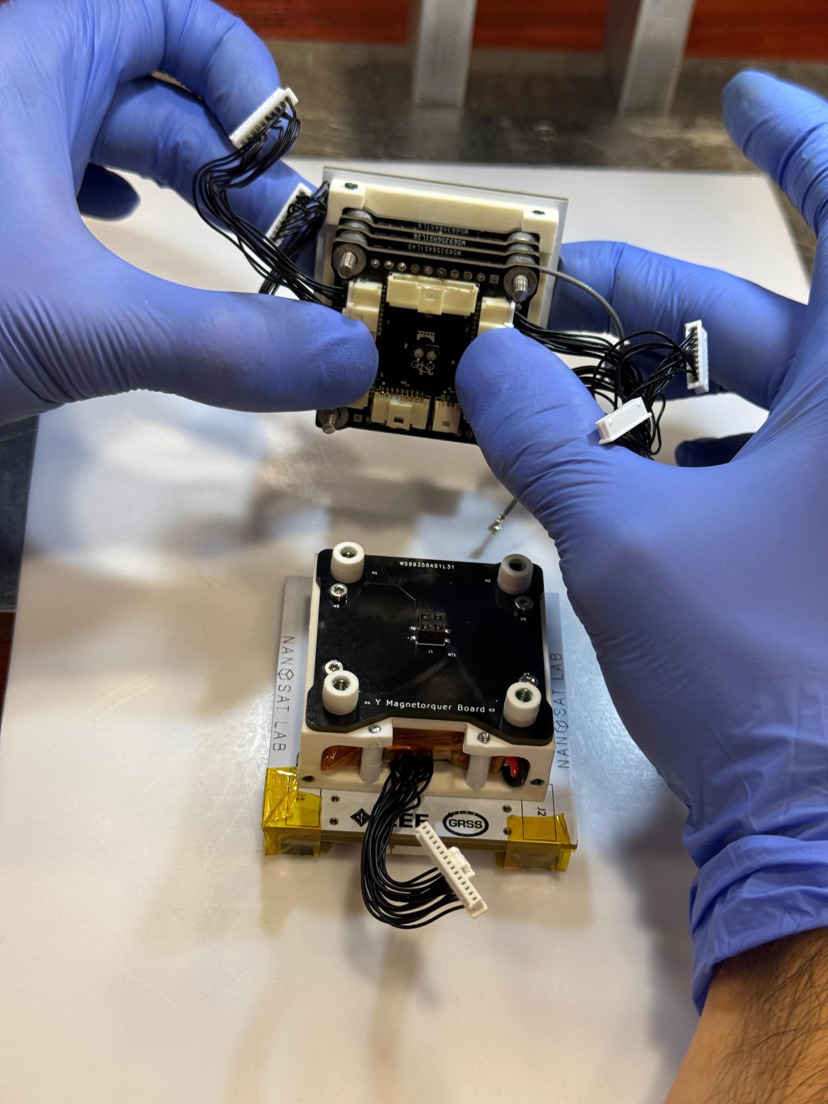](https://wiki.nanosatlab.space/uploads/images/gallery/2025-07/whatsapp-image-2024-11-13-at-20-04-06-1.jpeg) [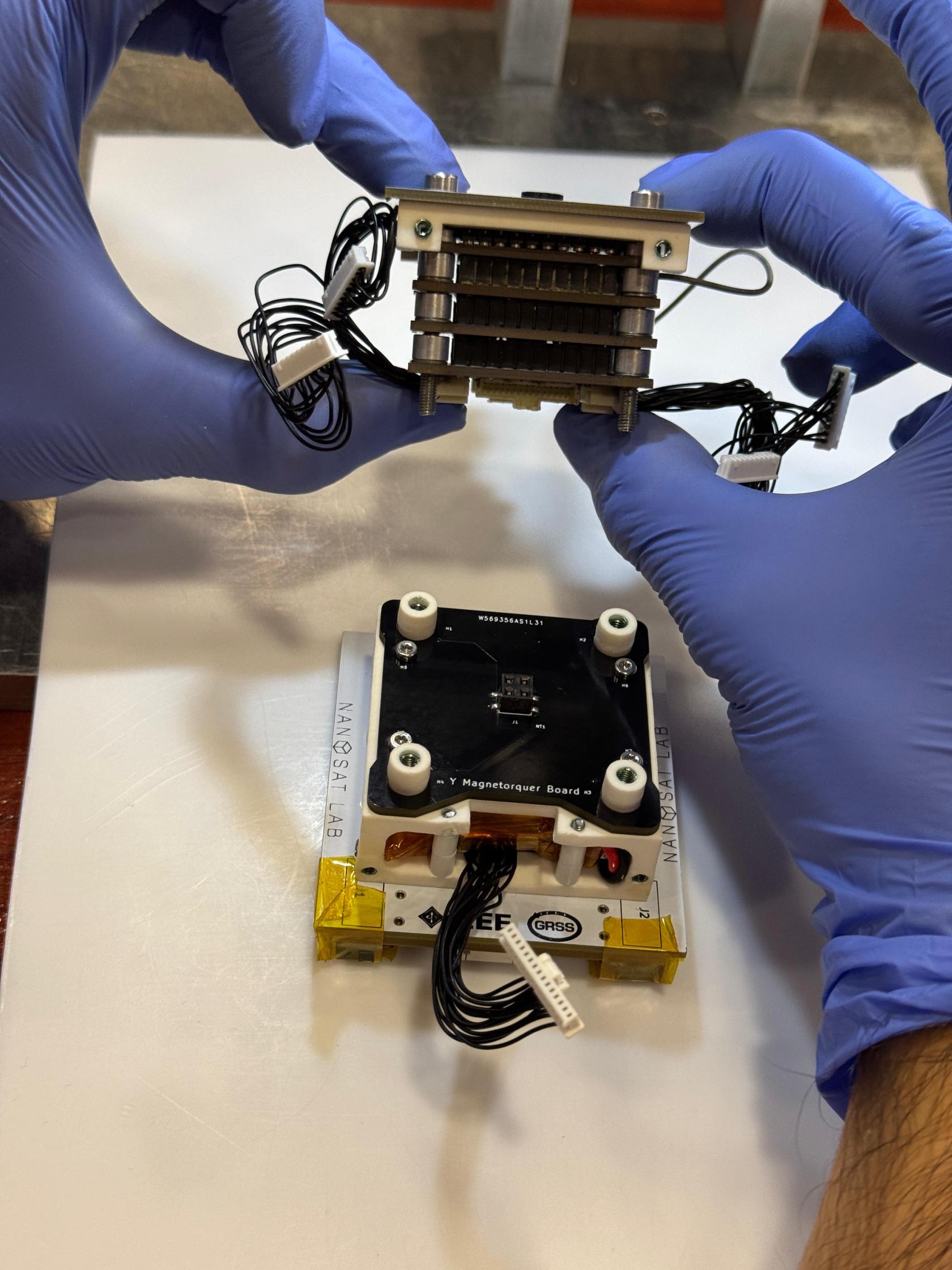](https://wiki.nanosatlab.space/uploads/images/gallery/2025-07/whatsapp-image-2024-11-13-at-20-04-06-2.jpeg) [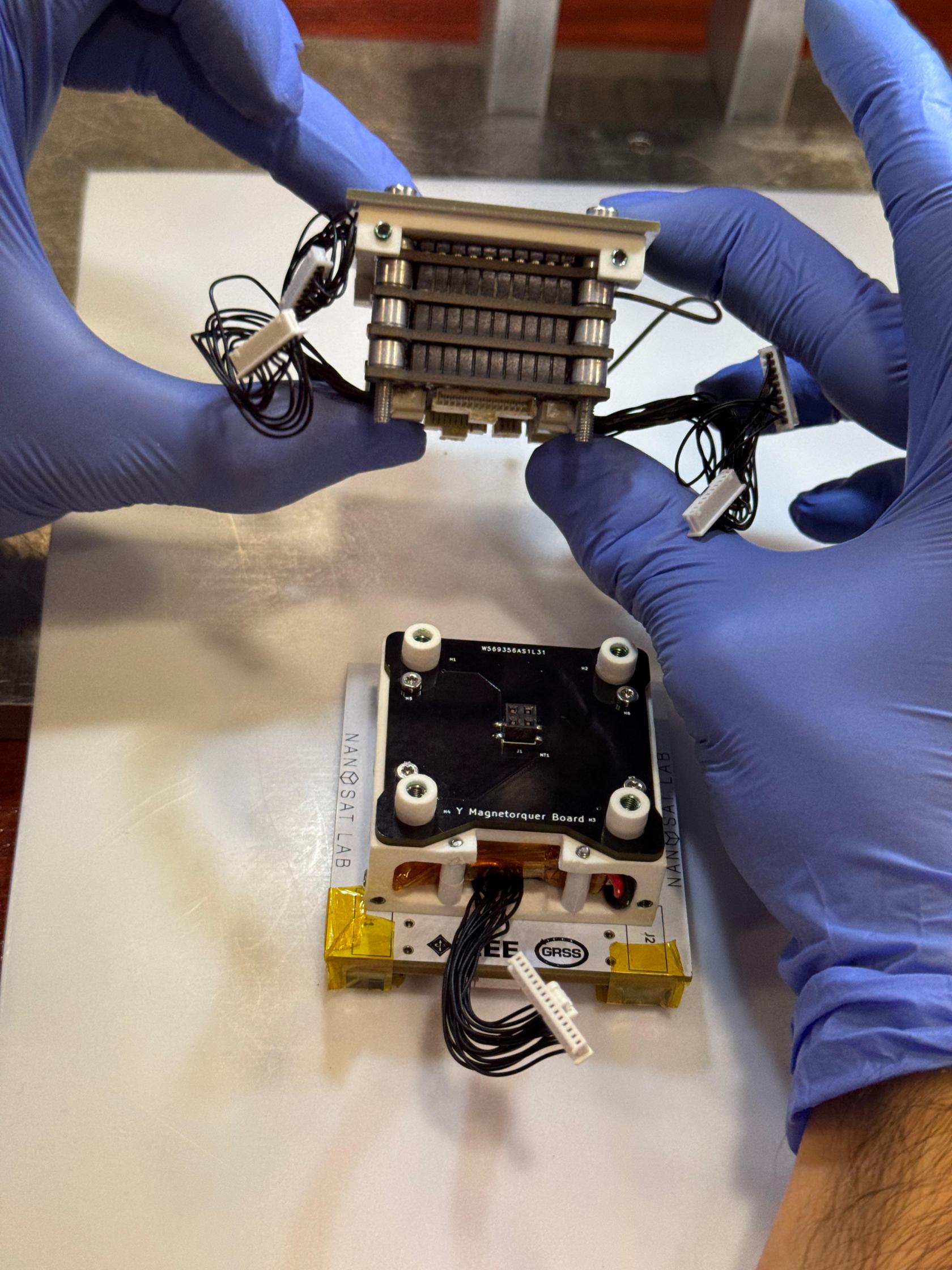](https://wiki.nanosatlab.space/uploads/images/gallery/2025-07/whatsapp-image-2024-11-13-at-20-04-06.jpeg) [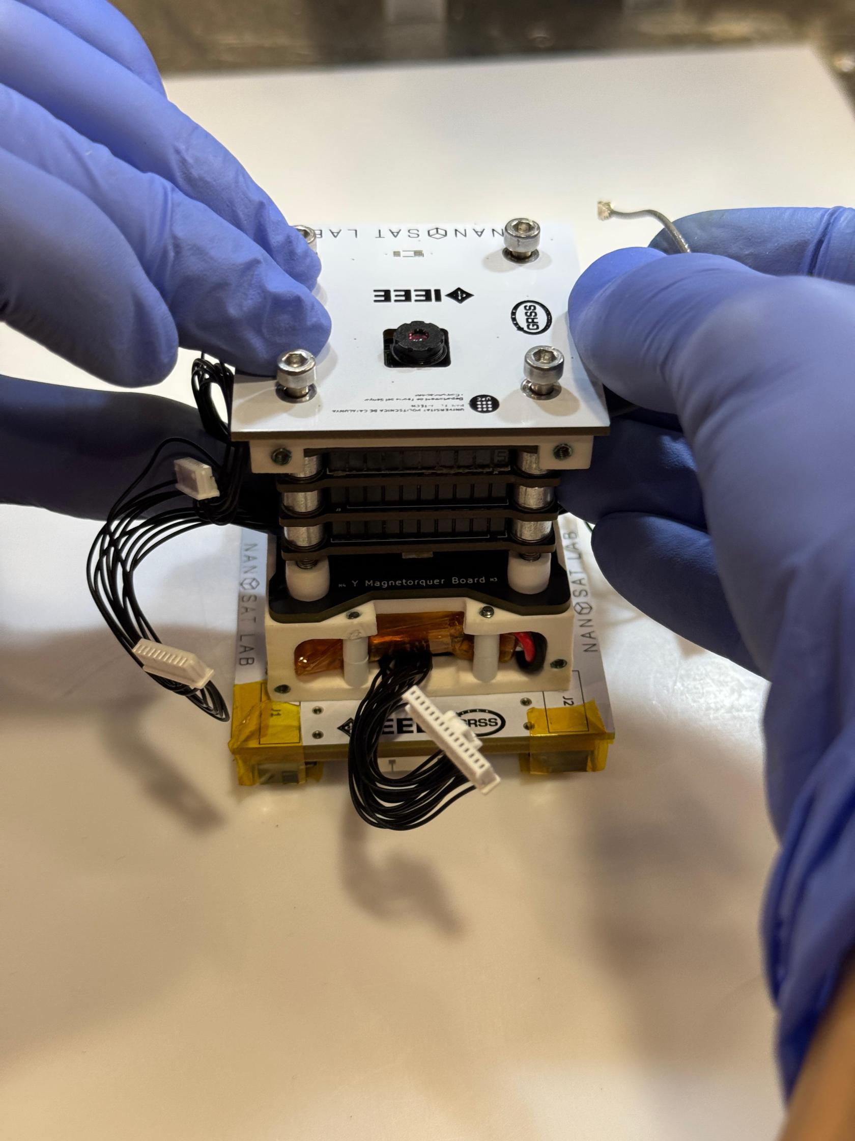](https://wiki.nanosatlab.space/uploads/images/gallery/2025-07/whatsapp-image-2024-11-13-at-20-04-07-1.jpeg) [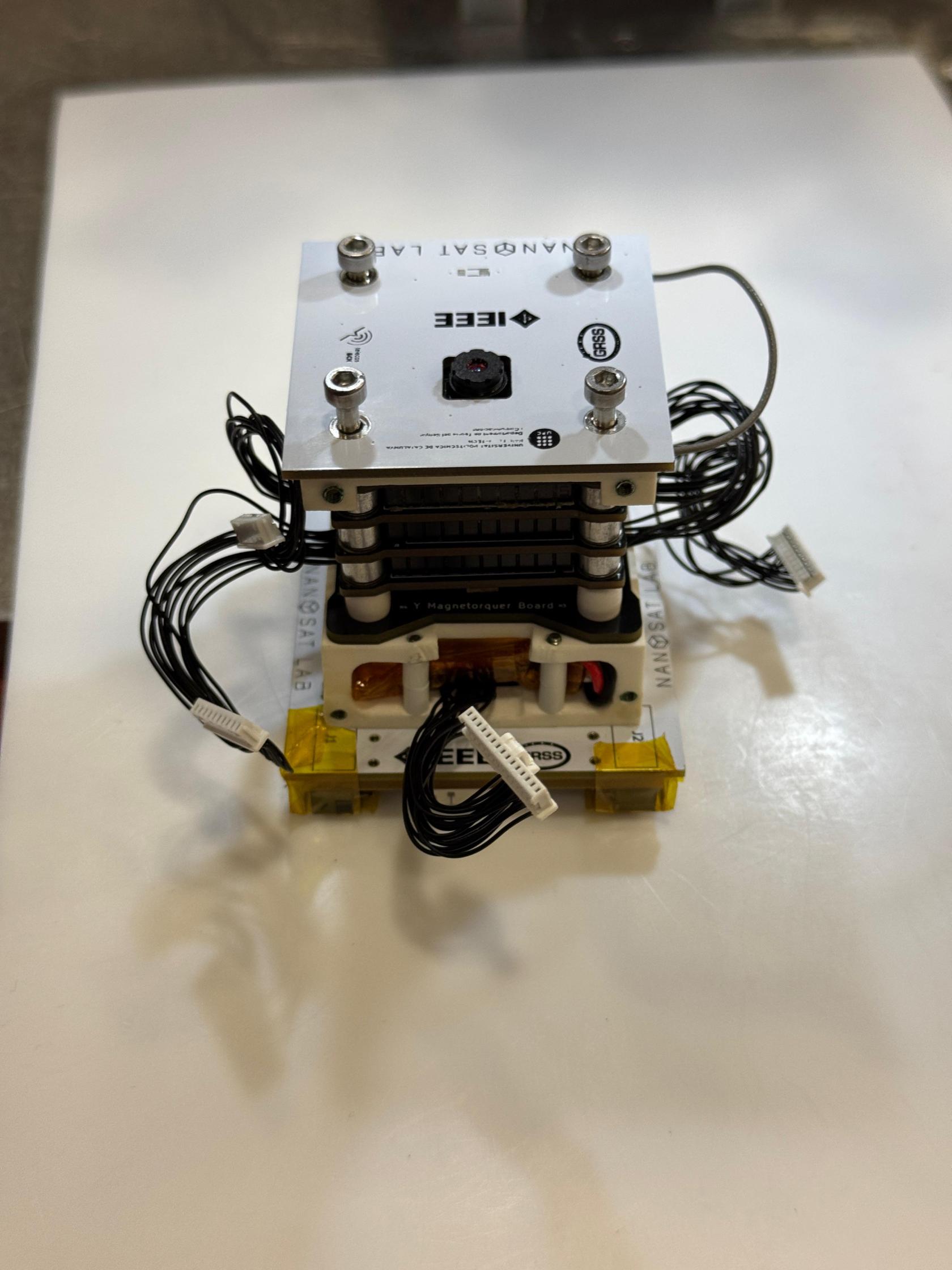](https://wiki.nanosatlab.space/uploads/images/gallery/2025-07/whatsapp-image-2024-11-13-at-20-04-07-2.jpeg) |
| 103 | Recall step 102 | Once both structures are properly positioned, tighten the screws to securely fasten them together. | Make sure that the 15-pin flat-wire faces the 15-pin connector coming out the battery aperture. | [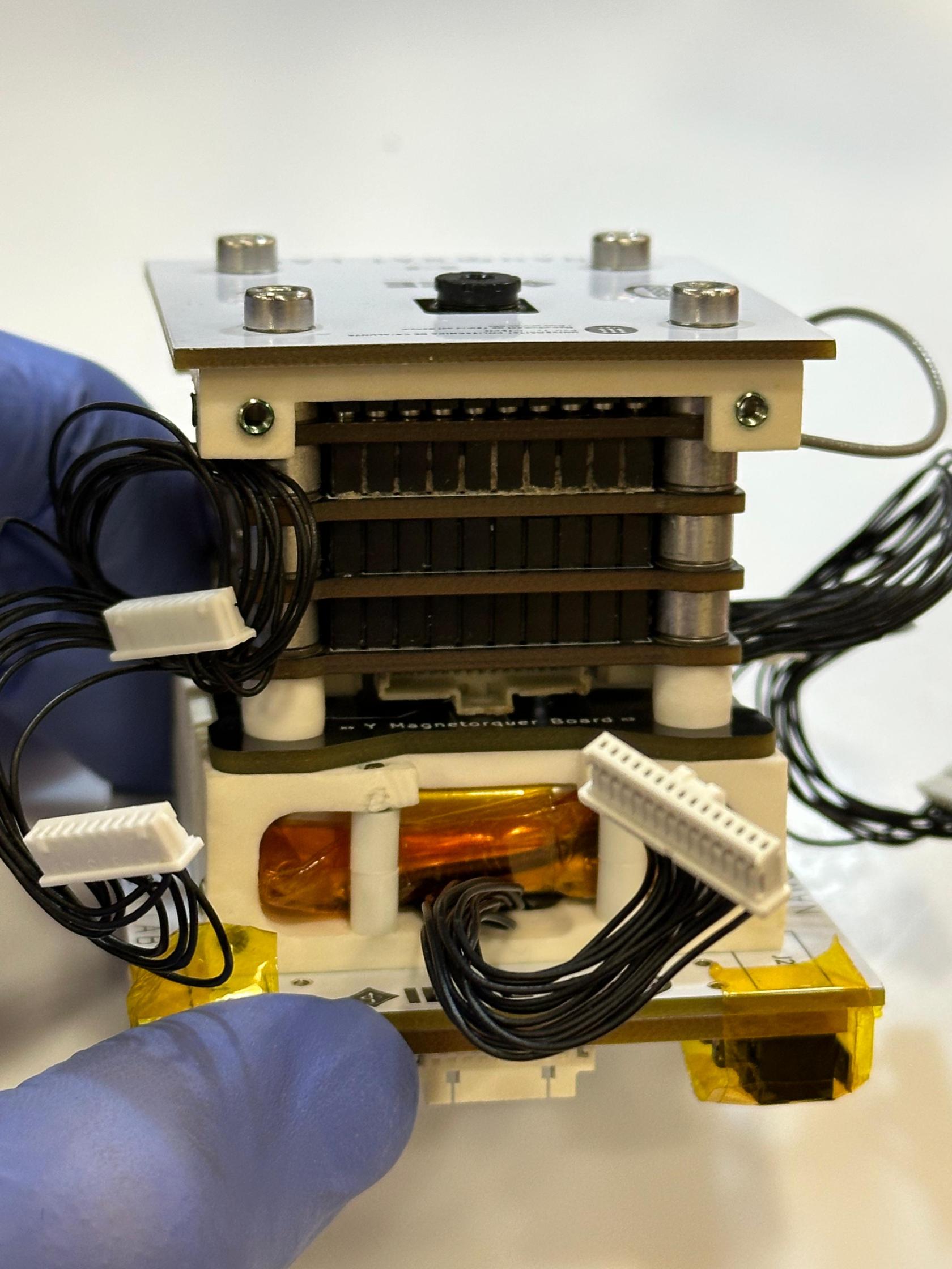](https://wiki.nanosatlab.space/uploads/images/gallery/2025-07/whatsapp-image-2024-11-13-at-20-06-18.jpeg) [](https://wiki.nanosatlab.space/uploads/images/gallery/2025-07/whatsapp-image-2024-11-13-at-20-07-00-1.jpeg) [](https://wiki.nanosatlab.space/uploads/images/gallery/2025-07/whatsapp-image-2024-11-13-at-20-07-00-2.jpeg) [](https://wiki.nanosatlab.space/uploads/images/gallery/2025-07/whatsapp-image-2024-11-13-at-20-07-00.jpeg) |
| 110 | Recall step 103 | Connect the 15-pin flat-wire from the inner battery structure to the 15-pin connector on the ADCS. This flat-wires come from the bottom PCBs and will be connected to the ADCS. | Ensure the wires pass through the opening as shown in the picture. | [](https://wiki.nanosatlab.space/uploads/images/gallery/2025-07/whatsapp-image-2024-11-13-at-20-13-27.jpeg) [](https://wiki.nanosatlab.space/uploads/images/gallery/2025-07/whatsapp-image-2024-11-13-at-20-12-36-1.jpeg) [](https://wiki.nanosatlab.space/uploads/images/gallery/2025-07/whatsapp-image-2024-11-13-at-20-12-36-2.jpeg) [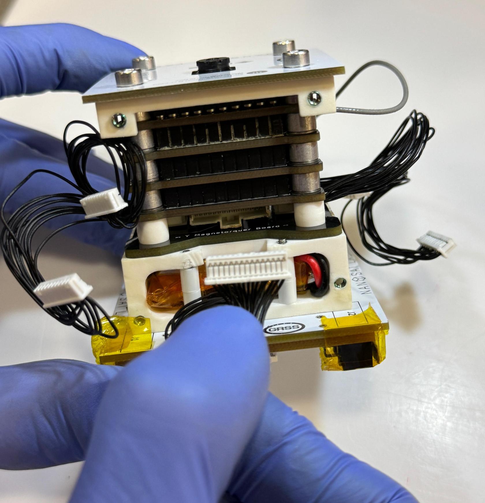](https://wiki.nanosatlab.space/uploads/images/gallery/2025-07/whatsapp-image-2024-11-13-at-20-12-36.jpeg) |
| 111 | Recall step 103 | Connect the 3-pin flat-wire from the inner battery structure to the 3-pin connector on the ADCS. This flat-wires are connected to an NTC and the battery heater and will be connected to the ADCS. | Ensure the wires pass through the opening as shown in the picture.
As it for now, this is not yet implemented to our assembly. | |
| 120 | 1 x PCB-12 1 x Full stacked PocketQube from step 111. 4 x SCREW-03 | Prepare the components. | Please note that these steps will be performed with side boards that do not have solar cells. Be cautious when handling solar cells, as they should not be touched. | [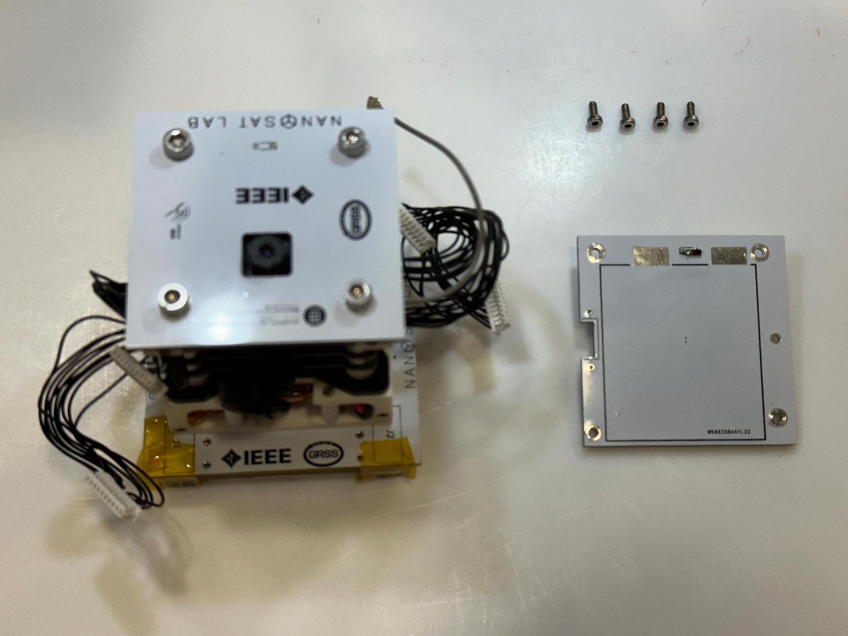](https://wiki.nanosatlab.space/uploads/images/gallery/2025-07/whatsapp-image-2024-11-13-at-20-25-35.jpeg) [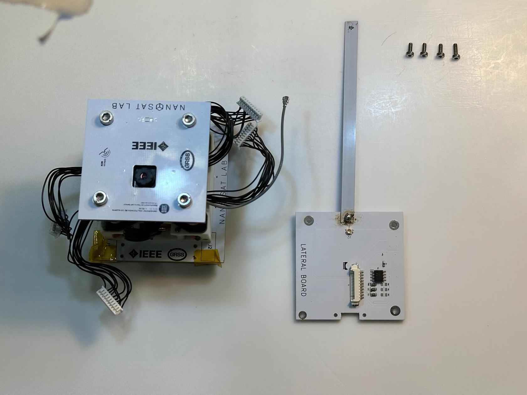](https://wiki.nanosatlab.space/uploads/images/gallery/2025-07/whatsapp-image-2024-11-13-at-20-47-11.jpeg) |
| 121 | 1 x PCB-12 with antenna 1 x Full stacked PocketQube from step 111. | Connect 10-pin PicoBlade flat-wire to the 10-pin connector from PCB-12. Additionally, connect the RF connector from the OBC-COMMS board to the RF connector of the lateral board with the antenna connected. | Each side board (PCB-12) will correspond to one of the orientations: +X, -X, +Z, or -Z, as specified in the respective side board assembly procedure. Each 10-pin PicoBlade flat-wire connector on the ADCS corresponds to one of these axis, so the side boards must align with the expected axis on the ADCS. | [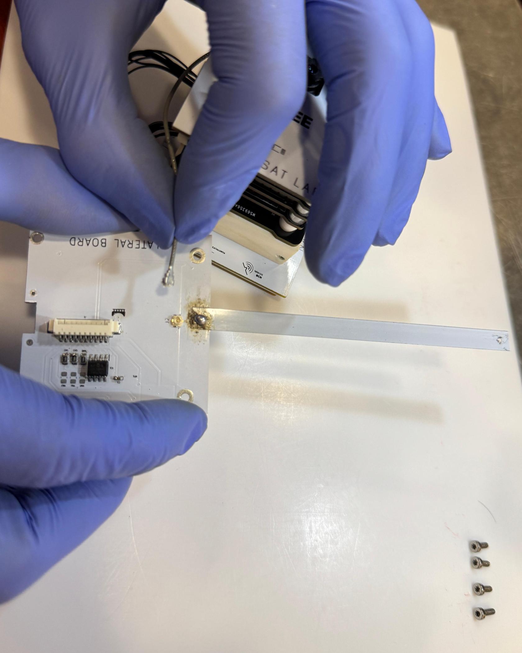](https://wiki.nanosatlab.space/uploads/images/gallery/2025-07/9vhwhatsapp-image-2024-11-13-at-20-51-32.jpeg) [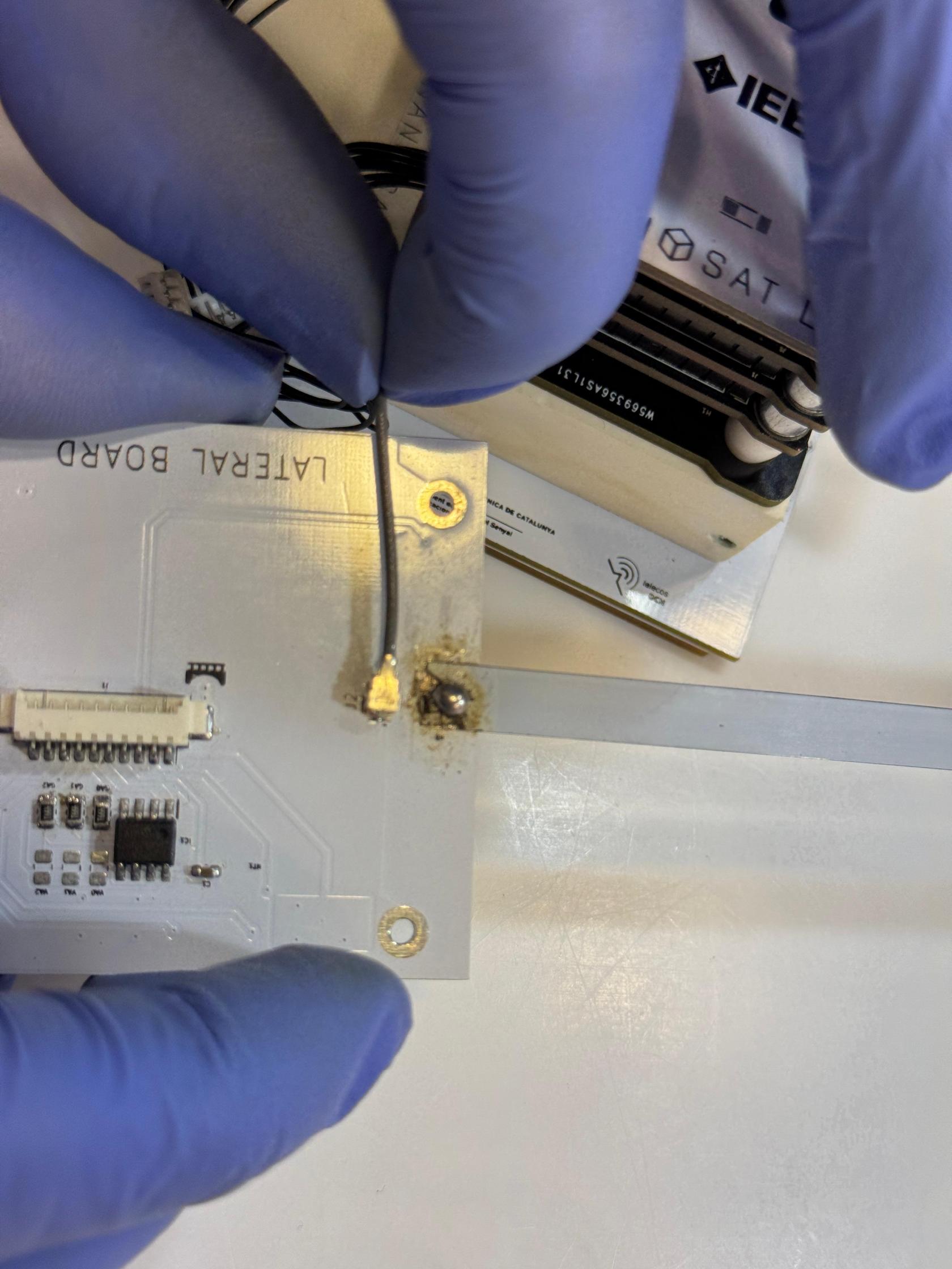](https://wiki.nanosatlab.space/uploads/images/gallery/2025-07/whatsapp-image-2024-11-13-at-20-51-32-2.jpeg) [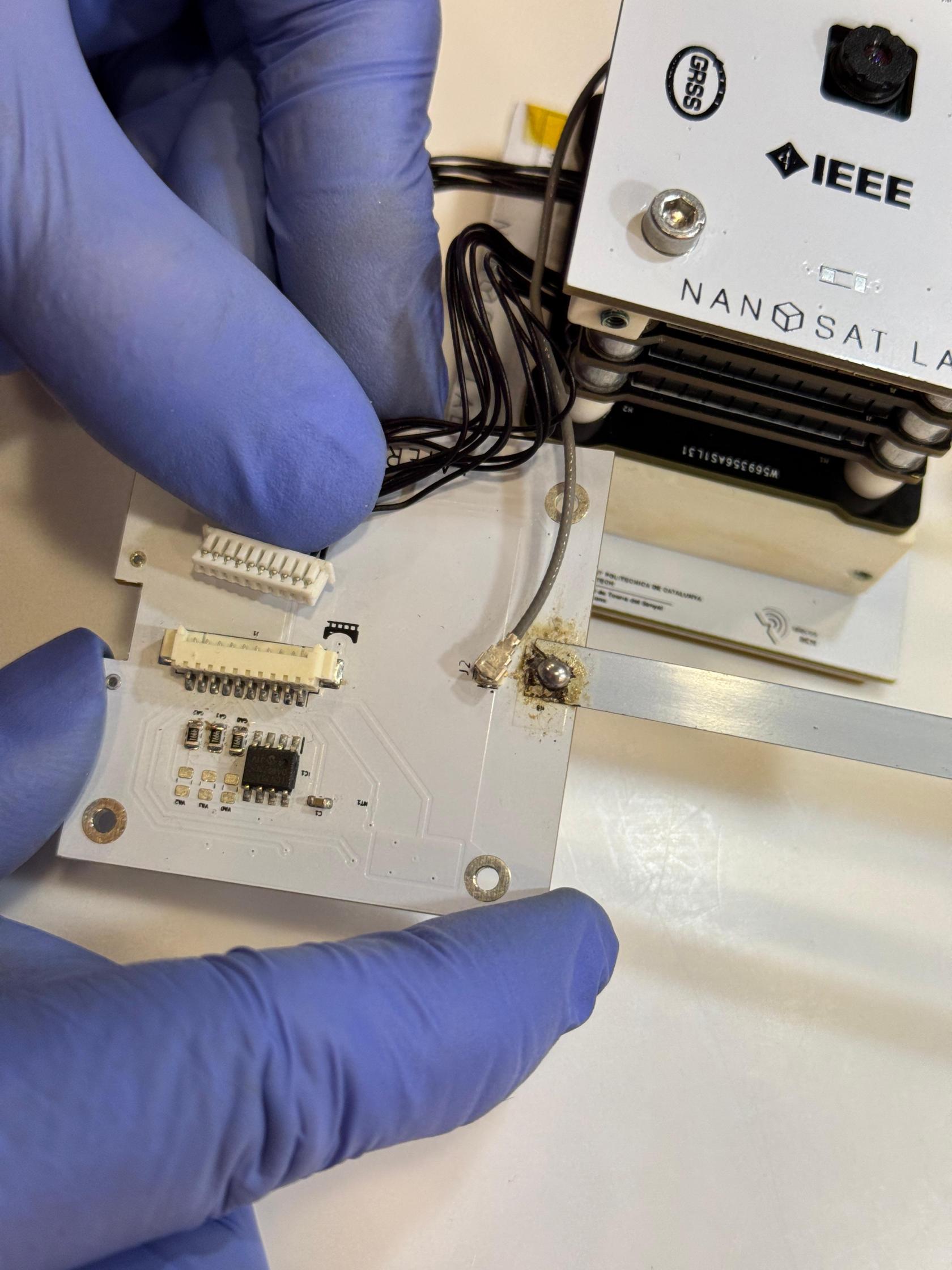](https://wiki.nanosatlab.space/uploads/images/gallery/2025-07/whatsapp-image-2024-11-13-at-20-51-32-3.jpeg) [](https://wiki.nanosatlab.space/uploads/images/gallery/2025-07/whatsapp-image-2024-11-13-at-20-51-32-4.jpeg) [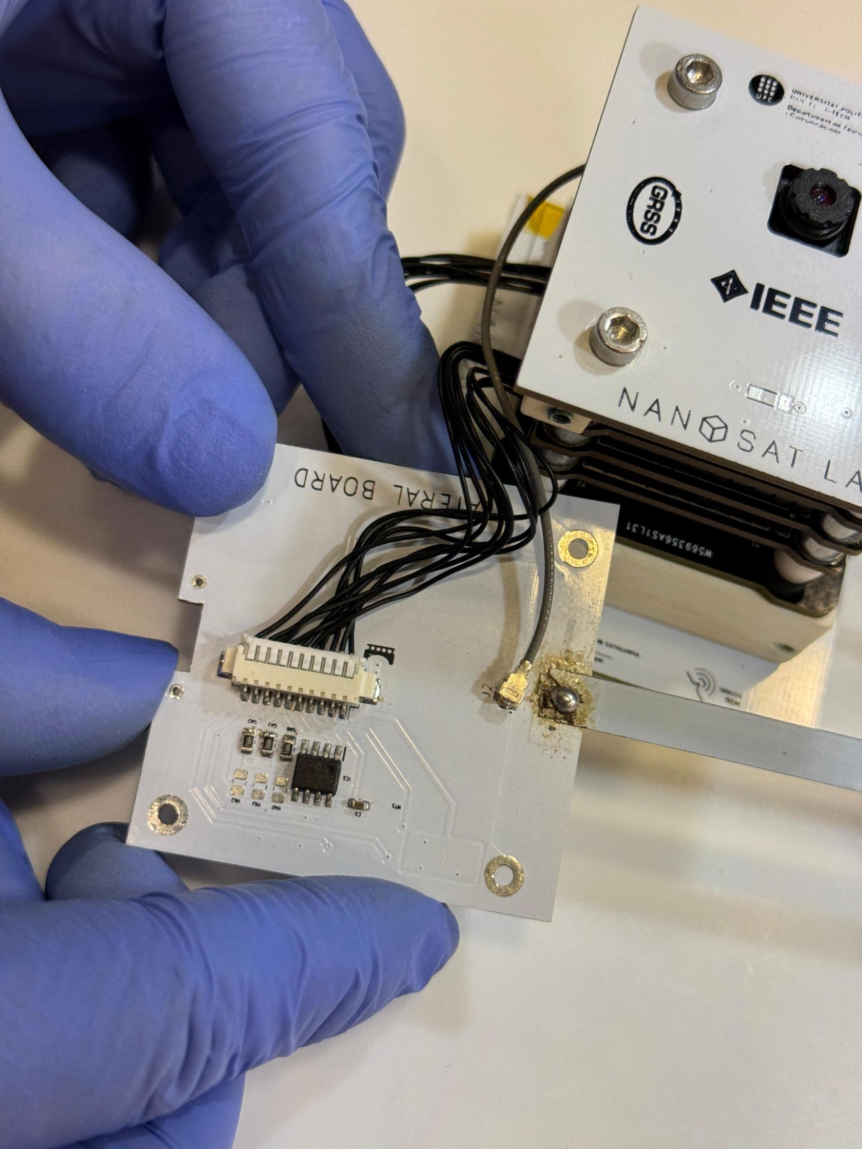](https://wiki.nanosatlab.space/uploads/images/gallery/2025-07/whatsapp-image-2024-11-13-at-20-51-32-5.jpeg) |
| 122 | Recall step 121 4 x SCREW-03 | After all connectors are attached to the side board, secure the side board to the full stack. | The cables between the stack and the side boards should be arranged in a loop-like configuration so that it doesn't stay sqeezed.
Make sure cables are not squeezed! | [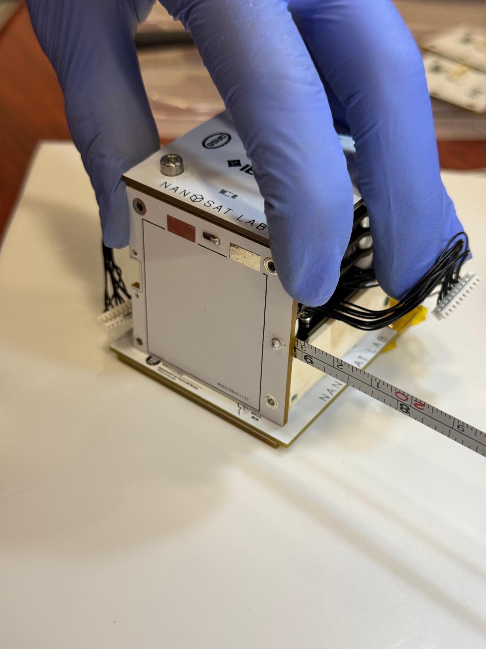](https://wiki.nanosatlab.space/uploads/images/gallery/2025-07/hz5whatsapp-image-2024-11-13-at-20-58-19.jpeg) [](https://wiki.nanosatlab.space/uploads/images/gallery/2025-07/whatsapp-image-2024-11-13-at-20-58-19-1.jpeg) [](https://wiki.nanosatlab.space/uploads/images/gallery/2025-07/whatsapp-image-2024-11-13-at-20-58-19-2.jpeg) |
| 123 | 3 x PCB-12 1 x Full stacked PocketQube from step 122. | Repeat step 121 with the remaining lateral boards. | Each side board (PCB-12) will correspond to one of the orientations: +X, -X, +Z, or -Z, as specified in the respective side board assembly procedure.
Each 10-pin PicoBlade flat-wire connector on the ADCS corresponds to one of these axis, so the side boards must align with the expected axis on the ADCS.
If you're having trouble fastening SCREW-03, ensure that SCREW-04 is properly tightened.
Make sure cables are not squeezed! See images. | [](https://wiki.nanosatlab.space/uploads/images/gallery/2025-07/whatsapp-image-2024-11-13-at-21-01-24.jpeg) [](https://wiki.nanosatlab.space/uploads/images/gallery/2025-07/whatsapp-image-2024-11-13-at-21-01-24-7.jpeg) [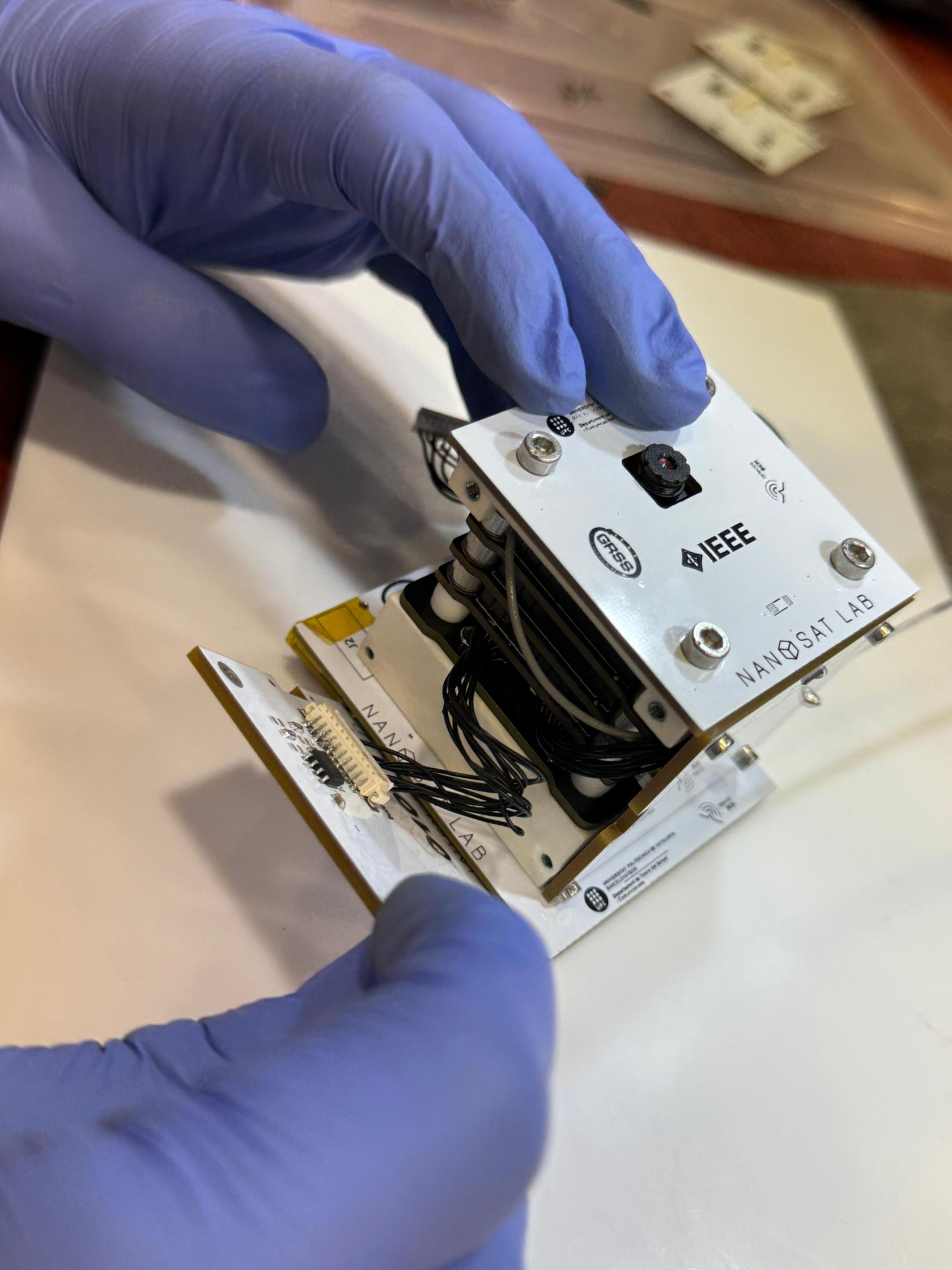](https://wiki.nanosatlab.space/uploads/images/gallery/2025-07/whatsapp-image-2024-11-13-at-21-01-24-6.jpeg) |
| 130 | 1 x Assembled PQ from step 123 1 x Dyneema | Mount the antenna deployment system using a dyneema. | Please refer to the specific tutorial. | |
| 140 | 1 x PQ | Assembly completed. | Congratulations! | [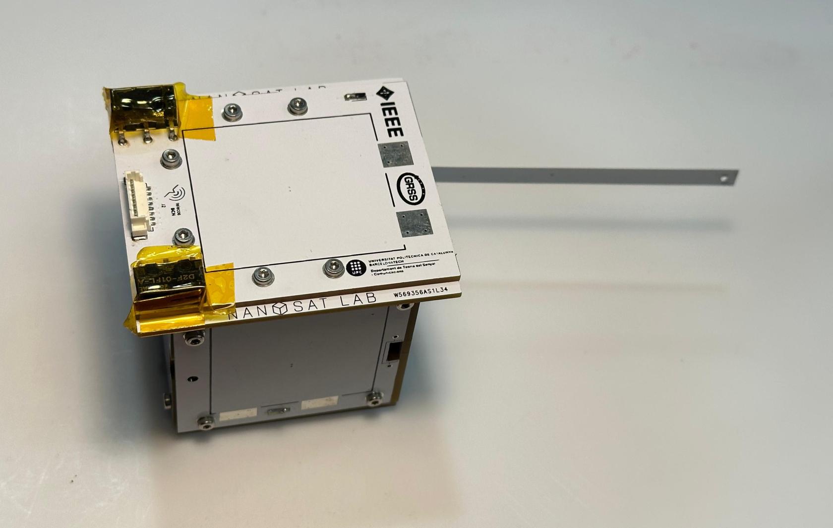](https://wiki.nanosatlab.space/uploads/images/gallery/2025-07/whatsapp-image-2024-11-06-at-18-17-58.jpeg) [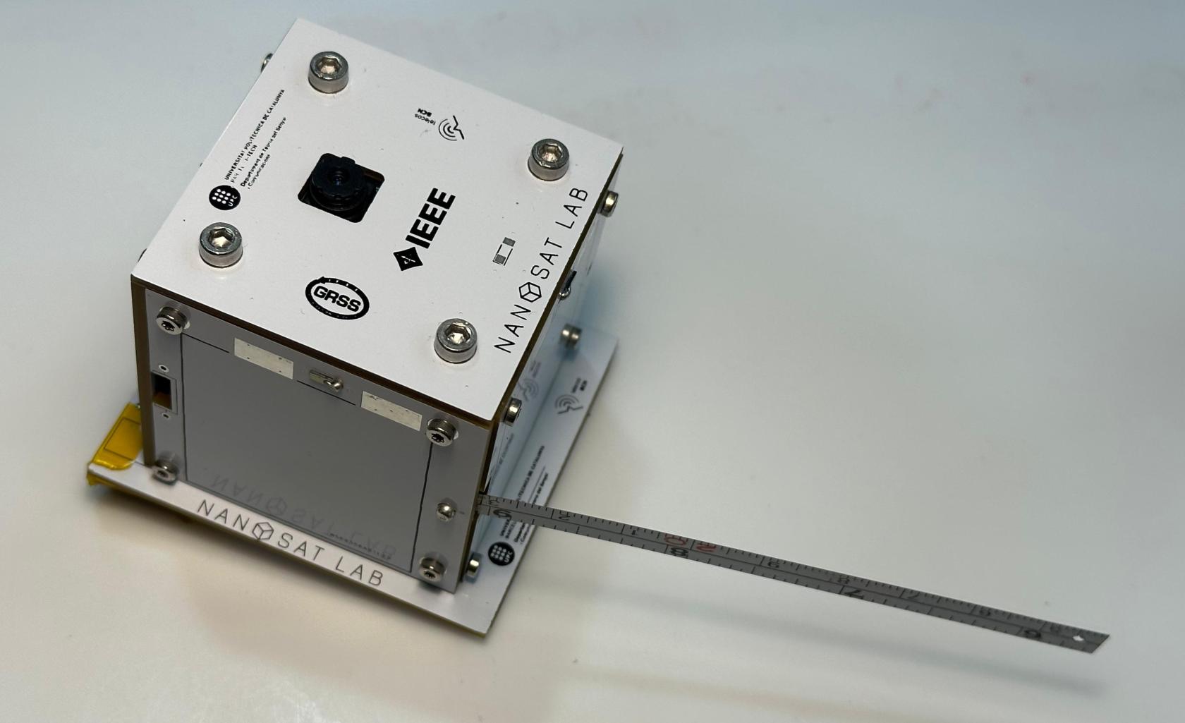](https://wiki.nanosatlab.space/uploads/images/gallery/2025-07/whatsapp-image-2024-11-06-at-18-17-59-1.jpeg) [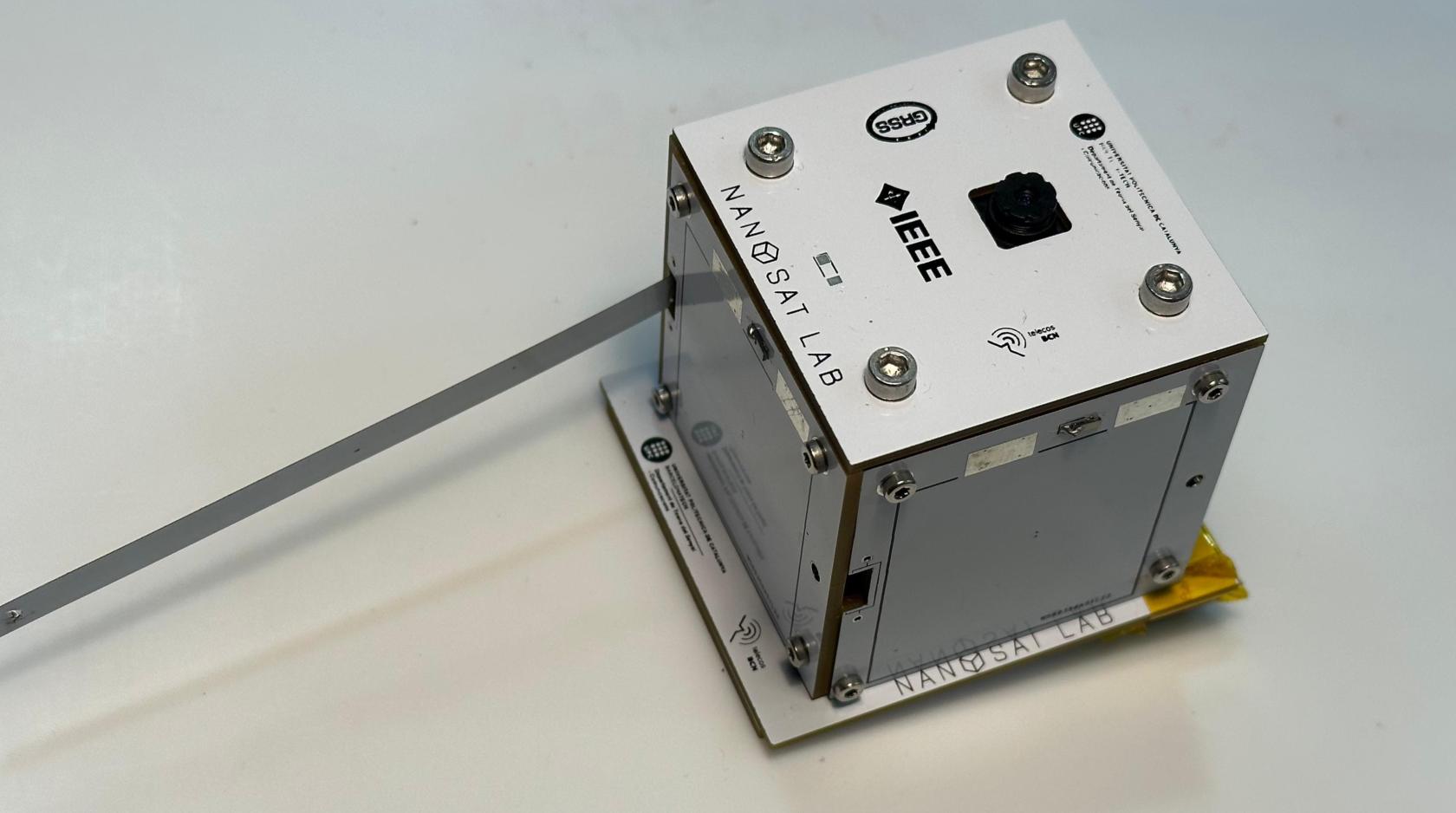](https://wiki.nanosatlab.space/uploads/images/gallery/2025-07/whatsapp-image-2024-11-06-at-18-17-59.jpeg) [](https://wiki.nanosatlab.space/uploads/images/gallery/2025-07/whatsapp-image-2024-11-13-at-21-04-44-1.jpeg) |