ᴾᵒCat: Introduction & Requirements
In this book a description of the Wiki and the IEEE Open PocketQube is given, providing some context into the development of the standard and the ᴾᵒCat spacecrafts itself.
A mission and system description is provided, as well as the requirements established for the Lektron mission. Do note that these will vary depending on your own mission as well as the changes made to the spacecraft systems, mainly, payload.
- Wiki Structure
- Introduction to the IEEE Open PocketQube Kit
- Mission Description
- System Description
- Requirements
Wiki Structure
This page presents the structure of this Wiki. It is structured as follows:
Introduction & Requirements
- Wiki Structure
- Introduction to the IEEE PQ Kit
- Mission Description
- Statement and Objectives
- Data products
- Mission phases
- Satellite Operational Modes
- System Description
- Physical Architecture
- Functional Architecture
- Spacecraft System Configuration
- Radiation protection
- Requirements
- Mission requirements
- System requirements
Mission Analysis and Characterizations
- Mission analysis
- Mission analysis report
- Link and Data budget analysis
- Link budget
- Data budget
- Space Debris Mitigation
- Space Debris Mitigation report
- Characterization and Calibration
- Solar cells
- Battery characterization test
- Battery degradation test
- Battery degradation test
- Photodiodes temperature characterization
- GYroscope characterization & calibration
- Magnetorquer polarisation verification
Structure & Subsystems
- Structure
- Subsystems (ADCS, EPS, COMMS, OBC)
- Description
- Hardware Design
- Software Design
- SSV
- Tests as run
- Electrical ground support equipment
- Wiring and setup
- Design specifications
- Mechanisms
- COMMS antenna deployer
- Killswitches
VGA Payload
- Description
- Hardware Design
- Software Design
- SSV
RFI L-Band Payload
- Description
- Hardware Design
- Software Design
RFI K-Band Payload
- Mission analysis and requirements
- Detection algorithms
- Software Design
- Block diagrams
- Payload design
- Antenna design
- Data acquisition
- RFI-Dedicated Thread
- Tests
- Tests as run
- Drone campaign
Operations
- Operations
- Mission phases
- Mission timelines
- Operational database
- Operational procedures
Procedures
- Assembly & Integration
- Helicoils
- COMMS antenna
- Assembly
Federated Satellite System Experiment
- Introduction
- Protocols
Introduction to the IEEE Open PocketQube Kit
Thanks to the introduction of the CubeSat standard in 1999 by professors J. Puig-Suari (California Polytechnic State University) and Bob Twiggs (Stanford University’s Space Systems Development Lab) in the past two decades, the number of satellites launched has increased exponentially. CubeSat’s were initially defined in a configuration called a 1U, that is equivalent to a cube of 100 mm side, with a mass of roughly 1 kg. However, recent revisions of the standard (Available here) increased the 1U mass to 2 kg, and allowed the possibility of different 1U combinations for 1U, 1.5U, 2U, 3U, 6U and 12U. The softer requirements of a CubeSat as compared to other conventional satellites has allowed organizations and institutions with limited resources to be able to launch their own payloads, operate their own missions, and reduce the mission required development time.
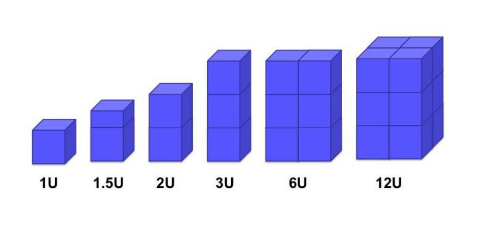
Figure 1.1 CubeSat Sizes. Illustration by NASA
Despite the reduced complexity of a CubeSat as compared to a conventional satellite, the difficulty in developing a CubeSat is still a barrier for some organizations that do not have the required facilities or knowledge, and cannot afford its cost. For this reason, the PocketQube specification was introduced in 2009, which proposed a pico-satellite with dimensions of 50x50x50 mm called a 1P unit, that is half the side or the eight of the volume of a CubeSat, with a mass smaller than 250 g. The first PocketQube was launched by the Morehead State University in collaboration with the Sonoma State University in 2013.
The objective of the PocketQube was to further reduce the spacecraft cost and complexity, while trying to maintain as much functionality as possible. This has been possible thanks to the improvement in commercially off-the-shelf (COTS) components. Despite not being specifically designed for space applications, they have shown to be fairly durable to space environmental conditions, as shown by the number of recent missions launched. Their mass production has also led to a reduction in cost, which favors the adoption of the PocketQube standard.
After the introduction of this new and smaller form factor, several companies and institutions have started using this new type of spacecraft for applications that have been mainly focused on IoT and EO, and it has also served as an educational tool for academic institutions and associations. The two leading companies in the use of PocketQube’s for space missions have been Alba Orbital and FOSSA Systems.
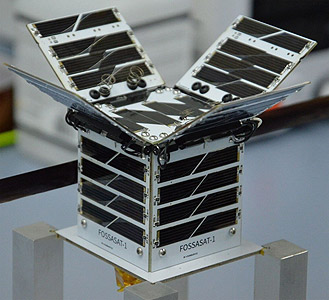
Figure 1.2 FossaSat1 [Fossa Systems]
Furthermore, the space harsh environment conditions make that not every solution is feasible. Spacecrafts experience high levels of radiation because of the lack of the Earth’s atmosphere that degrade materials at a higher rate and means that not all materials can be used, big temperature gradients stress materials and can damage electronics critically, single-event upsets can hang the on-board computer or corrupt memory, and the extreme vibrations experienced during launch can affect the structure and connectors.
These inconveniences combined might require a knowledge level and a number of resources that cannot be surmounted by some organizations that otherwise might want to design a spacecraft mission, turning into a barrier for new-comers to the space sector. Therefore, the GRSS-IEEE procured the development of the “IEEE Open-PocketQube Kit” as an educational initiative for all interested organizations that want to pursue a PocketQube and might not have the means to start.
For compatibility with commercial deployers, the PocketQube developed in this project follows the PocketQube mechanical standard. The standard specifies that the dimensions for a 1P pocket have to be of 50x50x50 mm, and that it has to be placed over a 64x58 mm interface board that will be used to hold the PocketQube inside its deployer. Despite that, the standard does not however specify the inner structure of the satellite. As a result, the “IEEE Open PocketQube kit” has been proposed as an alternative to reduce the entry barrier.
The “IEEE Open-PocketQube Kit” is an educational initiative proposed by the IEEE GRSS society to develop an open-source PocketQube kit to facilitate the entry barrier to organizations and institutions to space. Its design started in Spring 2020, and it has been carried by previous PAE and TFG students that worked in the development of the PocketQube that preceded this project.
The need to create an open-source PocketQube kit comes from the requests of new-coming institutions in the space sector that want to launch a satellite, but do not have the means to start their design from zero. The kit should provide the design resources necessary to be capable, for any unexperienced organization, to reproduce the structure and subsystems of one 1P PocketQube, and be able to integrate a custom payload. These includes the subsystems schematics, layouts and bill of materials, documentations and guides needed to elaborate a PocketQube.
Within the “IEEE Open PocketQube kit” project three different payloads will be developed and tested in three different PocketQube’s:
- ᴾᵒCat 1: carries a VGA camera,
- ᴾᵒCat 2: carries a L-band RFI monitoring payload,
- ᴾᵒCat 3: carries a Ka-band RFI monitoring payload to measure the possible interferences caused by the 5G communications system deployment.
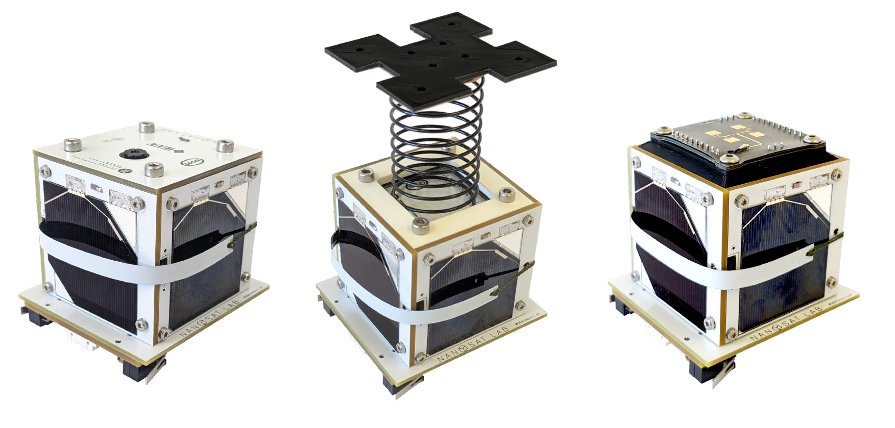
Figure 1.3 ᴾᵒCat 1, ᴾᵒCat 2 and ᴾᵒCat 3, the PocketQubes developed in the context of the IEEE Open PocketQube Kit project.
Mission Description
In this chapter several aspects relating to the ᴾᵒCat are described. Do note that these are intended to serve as a reference and may not be representative of your own mission.
Statement and Objectives
Mission Statement
The PoCat-Lektron is a mission resulting from the IEEE OpenPocketQube Kit initiative, developed at the UPC NanoSat Lab. The mission has been selected in the 4th call of the ESA Fly Your Satellite! (FYS) program. The mission analysis presented corresponds to the PoCat-Lektron mission. It consist of two 1P PocketQubes, the PoCat-2 and the PoCat-3, developed as a part of the IEEE OpenPocketQube Kit. This mission aims to demonstrate the feasibility of PocketQube platforms for remote sensing applications. The payloads on board of the PocketQubes are two passive radiometers to be use for RFI purposes on K and L bands. Apart from the remote sensing nature of the mission, this mission also aims to demonstrate the feasibility of the PocketQube platforms to create, manage and join Federated Satellite Systems. To do so, the FSS Experiment will be reproduced as a part of the experiments of the mission.
Mission Objectives
1. Demonstration of Scientific Viability: Demonstrate the feasibility of conducting scientific missions using PocketQube platforms. To do so, the mission proposes collecting valuable RFI data through a K-Band and L-Band passive radiometers (One for each PocketQube). The payloads will monitor interferences on these bands. This data will facilitate enhanced detection and the generation of heatmaps indicating RFI distribution across the globe. In this experiment we aim to obtain data on the K-Band to see the impact on the atmospheric water vapor measurements, and in the L-Band the interferences over the Position Navigation and Timing (PNT) signals.
2. Satellite Federation Concept: To establish and demonstrate that PocketQube platforms can create, manage and join Federated Satellite System (FSS). This proof of concept for this resource-limited platforms is based on the reproduction of the FSS Experiment conducted at the UPC NanoSat Lab. The demonstration consist on create a federation between 2 PocketQubes, in order to download data. Previous missions such as the FSS-Cat from the UPC NanoSat Lab demonstrated the feasibility of this opportunistic collaboration using 6U CubSats.
3. Educational Development: As a mission developed at the UPC NanoSat Lab, the mission is oriented for undergraduated students to gain experience and get involved in real space missions. In addition, several Bachelor and Master Thesis had been done from this project, apart from the academic papers that this project has produced.
Data Products
This section will cover the pata products generated by the Lektron mission. Consider these will vary depending on the P/L. The following information is presented in relation to ᴾᵒCat 1, ᴾᵒCat 2 and ᴾᵒCat 3.
Mission Data Products
The satellite mission will provide time-tagged, geolocated spectrograms and statistical data on Radio Frequency Interference (RFI) for both K-Band and L-Band. These bands are integral to a variety of critical applications:
- L-Band is primarily used for environmental monitoring, including soil moisture measurement, ocean salinity estimation, and sea ice thickness determination, all performed via microwave radiometry. It is also crucial for satellite navigation and GNSS reflectometry applications.
- K-Band supports atmospheric water vapor monitoring, short-range radar systems, and newly added 5G services.
The mission will also provide images on the visual spectrum, serving as a proof of concept for future PocketQube payload development and allowing the monitoring of large areas in critical enviromental states such as giant ice masses are rainforests. This task is performed by a VGA camera.
Scientific and Technological Questions to be Answered
The mission aims to enhance the understanding of electromagnetic spectrum occupancy in space. By providing RFI detection data, it will address key challenges related to spectrum interference regarding the impact of RFI on both communication and remote sensing. The data will also inform strategies for interference mitigation and spectrum optimization, ensuring the continued viability of K and L-Band applications.
The mission also aims to prove the feasibility of optical imaging by PQs.
Framework for Processing Mission Data Products:
RFI Data:
- Characteristics: Time-tagged geolocated spectrograms for K and L-Band frequencies.
- Sampling Frequency: High enough to allow detailed interference analysis and mitigation strategies. Specifically allowing for a high-resolution interference heatmap on ground.
- Ground Infrastructure: Data will be processed through a dedicated ground segment with advanced RFI detection capabilities, enabling both real-time and post-mission analysis.
- Data Volume:
- K-Band: 2.8KB per measurement.
- L-Band: 0.7KB per measurement.
- Accessibility: Data will be made available to certain stakeholders involved in the scientific sector like FARS and GRSS, promoting the collaborative development of spectrum usage strategies.
Optical Data:
- Characteristics: Time-tagged geolocated images of different Earth regions.
- Sampling Frequency: As defined by the operator.
- Ground Infrastructure: Data will be processed through a dedicated ground segment, enabling both real-time and post-mission analysis.
- Data Volume: Ranging from 2KB to 48KB. (more information provided here)
- Accessibility: Data will be made available to certain stakeholders involved in the scientific sector like FARS and GRSS.
Telemetry Data:
The satellite will generate telemetry data, including measurements of voltage, current, temperature, angular speeds, light intensity, and the Earth’s magnetic field. This data, although not commercially valuable, will be critical for assessing the operational state of the satellite and gaining insights into its long-term performance. The telemetry will be processed in near real-time and used to ensure optimal satellite functionality.
Services Provided:
The primary service offered by the mission will be comprehensive RFI data for K and L-Bands, enabling stakeholders to mitigate interference effectively, as well as close to real time Earth imaging. Additionally, the mission will provide operational health data for satellite performance monitoring, which will benefit satellite designers and operators for future missions.
Mission Phases
The mission is segmented into five distinct phases: 1) Prelaunch, 2) Launch and Early Orbit Phase (LEOP), 3) In-orbit Commissioning, 4) Operations, and 5) Post-mission. Throughout each phase, various procedures are carried out, either commanded from the ground or autonomously performed by the satellite. This section delineates the expected duration of each phase and specifies the actions performed and how they are executed.
1) Prelaunch Phase: This preliminary stage, will take place between one and six months prior the launch, and is estimated to span approximately two days. Involves performing tests and validation processes to guarantee the proper functionality of all subsystems, right up until the satellite is integrated into the deployer. Moreover, meticulous visual examinations will be performed on the satellite’s outer components to confirm they are in good conditions and have not suffered any damage. Upon completion of these final checks, the final software configuration parameters are uploaded, and all counters are reset to initialize the satellite in its initial flight conditions.
2) Launch and Early Operations Phase: This phase, which lasts about 10 hours, is autonomously handled by the spacecraft, starting after the launch, with the satellite being dispatched into space. Following deployment, the satellite’s kill switches are deactivated, and it powers on automatically. Initially, the satellite remains in standby mode for the first 30 minutes to prevent collisions with other satellites or debris. Subsequently, the satellite may initiate Attitude and Determination Control Subsystem (ADCS) activities to stabilize itself while concurrently attempting to deploy the communication antenna. However, it will delay initiating periodic beacon transmissions until 15 minutes later (45 minutes post-deployment), adhering to requirements prohibiting radio emissions beyond this time. These periodic beacons facilitate ground tracking of the satellite.
3) In-orbit Commissioning Phase: This phase begins after the ground station receives the first beacon from the satellite which means that commanding from the ground can start. Is estimated to last less than a week. The telemetry data contained in the beacon allows operators to verify the satellite’s and all subsystems’ correct operation and the successful execution of LEOP autonomously by the satellite. Assuming no issues arise, operators can start sending specific commands such as ”PING” to acknowledge signal reception and initiate communication, ”UPDATETIME” to synchronize the satellite’s clock, and ”UPLOAD TLE” for orbital data proposes. Additional configurations and checks are performed, including payload antenna deployment. Once stabilized and operational, the satellite commanded by the ground, will undergo experimental testing and calibration, transitioning to the operational phase.
4) Operational Phase: The fourth mission phase, Operations, is where the satellite is expected to spend most of its orbital lifetime, approximately one to two years. During this phase, the satellite’s health is monitored, payload operations are scheduled and executed, and housekeeping tasks are performed to maintain the satellite’s functionality.
5) End of Life and Post-mission Phase: The final phase begins once the team decides to conclude operations, either because the payload is no longer functioning correctly or the satellite can no longer operate. Expected to commence after about two years of operations, the satellite enters a passivation state, gradually depleting its energy until battery exhaustion or atmospheric re-entry. During this phase, the Federated Satellite Systems (FSS) may remain operational, providing services to nearby satellites thorough a federation agreements.
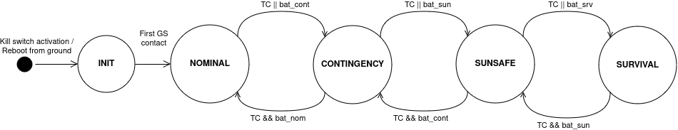
Satellite Operational Modes
The operational modes for the satellite and its subsystems are:
Init: This mode is directly associated with the LEOP. The LEOP phase is the most critical, as it begins when the satellite is deployed and concludes when the Communications (COMMS) antenna is deployed and contact with the ground segment is established. For the ᴾᵒCat mission, it includes the following steps in this order:
- Standby: To comply with the requirements, after injection in orbit the spacecraft must wait a minimum of 30 minutes before beginning operations or deploying appendages, specifically the COMMS and payload antenna. At the same time, no radio emissions are permitted after the spacecraft has been integrated into the PocketQube deployer, and this restriction remains in effect for 45 minutes following deployment. Therefore, no beacon transmissions are allowed. This precaution is necessary to prevent interference with other satellites being deployed or with other systems on the rocket. To meet these requirements, the satellite will wait 45 minutes before commencing operations and communications.
- Deployment of the LoRa Antenna: As mentioned, it is necessary to deploy the COMMS antenna to begin transmitting beacons, which will facilitate the first contact with the GS (Ground Station).
- First Contact with the Ground Station: The satellite will remain in this state until it receives confirmation from the GS that everything is functioning correctly, at which point nominal operations can begin.
- Nominal: If all the performance criteria and actions of the Init phase are successfully completed, the satellite enters into nominal mode. This mode serves as the default operating state in the best-case scenario, and the satellite remains in this mode as long as the batteries are above a certain threshold value. While in nominal mode, payload-related operations can be conducted, including the mission experiments, and the FSS.
Contingency: The satellite enters this mode when the batteries fall below a certain value. In this mode, some functionalities of the flight software are disabled, including the experiments conducted by the payload and the FSS. Also, the ADCS subsystems stop performing nadir pointing to reduce power consumption.
Sunsafe: This mode is associated with a critical condition of the satellite and is activated when the batteries drop below an even lower threshold. More restrictions are applied in this mode to further conserve energy. The Electrical Power Subsystem (EPS) and ADCS subsystems cease all activities, such as heating the batteries in the case of the EPS or dumping and detumbling in the case of the ADCS. These subsystems enter a passive
Survival: This final state is the most critical, occurring when the satellite lacks sufficient energy to perform any vital actions. It may also arise if a significant error occurs in the code, making it safer to remain in this state until operators determine the best course of action. In this state, all subsystems remain active but are only polling information from the sensors. At the same time, transmissions are ceased, and no beacons are transmitted to prolong battery life; the COMMS subsystem is only in reception mode.
The Figure 1.1 illustrates the transitions between the states. From the Init state, which is the first state the satellite enters after being released by the deployer or after a reboot, the satellite will transit to the Nominal state following the first contact with the ground segment. Once the satellite exits this state, it can only re-enter if a reboot event occurs.
All other states can transition up or down to the adjacent state. Transitioning to a state with more restrictions can occur automatically if the satellite does not have enough energy to remain in the current state, or it can be triggered by operators through the reception of a telecommand. Conversely, to transition to a less restrictive state, two conditions must be met: the battery level must be appropriate, and the satellite must receive a telecommand requesting the change of state.
System Description
In this section an overview the IEEE Open PocketQube is given going into detail of the physical and functional architecture. Spacecraft configuration and radiation measures are also presented.
Physical Architecture
The physical architecture of the spacecraft (S/C) is comprised by the different subsystems and components, as well as the electrical lines that provide communication between them. A PocketQube architecture is relatively simple compared to bigger spacecrafts, even when compared to CubeSats. The system straightforwardness is given by the use of an individual Microcontroller Unit (MCU). This approach, while necessary due to power and space (size) constraints, centralizes the S/C, and, while it creates a single point of failure to be very careful of, it also minimizes complexity.
A block diagram of the spacecraft (ᴾᵒCat 3) physical architecture is provided up next:
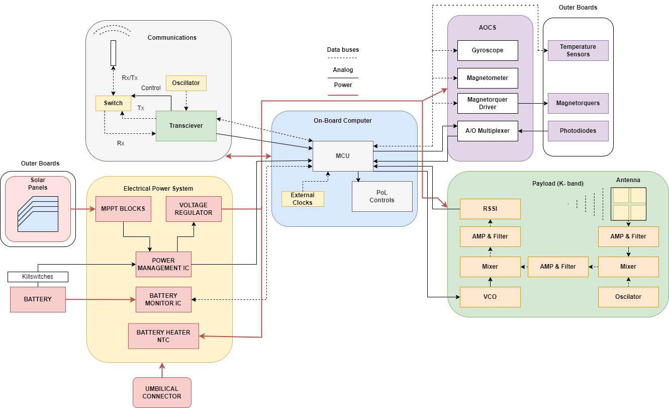
While it may appear complicated at first sight, this diagram should cause no fear once each subsystem (SS) is properly understood. To get some insight into the later a simple explanation of each SS component:
Communications (COMMS)
The COMMS subsystem main fuctions are to receive and send data through radio frequency (RF) waves. To do so it is provided of a monopole quarter-wavelenght antenna, with an approximate lenght of 8.6cm, designed to transmit at 868MHz. The signals to be sent by the spacecraft (telemetry) are generated and modulated by the transciever (combination of a radio transmitter and receiver). The signals received are also demodulated at the transciever.
The system is half-duplex as radio information (transmission and reception) can not be Tx'd and Rx'd at the same time. This is due to both the transicever capabilities and the use of a switch. The later regulates wether information is to be received or transmitted, and is controlled by the transciver itself which is, at the same time, controlled bu the MCU. In fact, all transciver control is done by the MCU through a Serial Peripheral Interface (SPI).
Note that the transciever requieres of an oscillator that provides a stable reference frequency.
Electrical Power System (EPS) & Power Generation
The EPS subsystem manages power distribution and regulation. Energy is obtained into the system through solar panels located at the lateral boards of the PocketQube. This energy is regulated by the MPPT blocks, one for each panel, and subministrated to the battery. Note that the killswitches ensure the satelite can't turn on when in it's rail before being deployed.
Power is distributed to the rest of the system after passing through the voltage regulator. Note that a battery heater is located in this board. The heater ensures that the battery temperature is constrained to higher than it's lowest operating temperature.
Finally, power can also be provided through the umbilical connector, still passing through the killswitches. The umbilical connector also provides code flashing into the MCU.
On-Board Computer (OBC)
The OBC subsystem's main component is the microcontroller unit (MCU). The MCU is in control of all data handling and on-board processing, acting as the brain of the spacecraft. Almost all information goes to or comes from the MCU and it is all stored there, either in its flash memory or in its random access memory (RAM).
Physically, on the OBC board will also be located the COMMS subsystem as well as point of load (PoL) controls and external clocks to ensure the proper timing of the MCU.
Attitude Determination and Control (ADCS)
The ADCS subsystem is the responsible for, as the name indicates, attitude determination and control. To do so it is equipped with a gyroscope, to measure it's angular velocity, a magnetometer to measure the local magnetic field, the magnetorquer driver, which controls the intensity that circulates through the magnetorquers, square, plain coils located at the lateral boards that provide torque via electromagnetic interactions, as well as an A/O Multiplexer that provides information on sun position.
Temperature sensors are also placed on the lateral boards in order to provide insight for future missions, as a tumbling mode to avoid heat is not possible with the current architecture.
Payload/K-Band (P/L)
The payload on ᴾᵒCat 3 measures RFI interference on the K-Band. To do so it is equiped with a patch antenna, several amplifiers and filters as well as mixers, one regulated by an oscilator and the other by a voltage controlled oscilator (VCO).
As mentioned several times, the architecture of this specific subsystem is completely dependant on the P/L. Note: RSSI means received signal strenght indicator.
Functional Architecture
The functional architecture of the spacecraft is defined by the different tasks or functions that each subsystem is designed to do. To this extent, all the operations done by the S/C can be categorized into the block diagram provided up next:
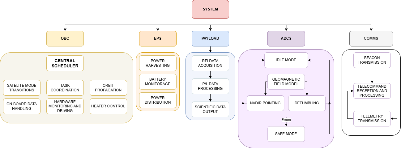
As it was done on the physical architecture explanation let's take a dive into the different parts in order to get a general overview. More information of each SS functionalities is found on their corresponding sections of the Wiki.
On-Board Computer (OBC)
The OBC is responsible for scheduling the different functions of the satelite. This is done through the coordination and control of software defined tasks programmed by the team. The OBC task itself is responsible of satelite mode transitions but the overall denominator of On-Board Software includes orbit propagation, housekeeping data management and On-Board data handling, heater control among other functionalities.
Electrical Power System (EPS)
The EPS is the subsystem responsible of power harvesting and maganagement, while also keeping track of the overall state of the required hardware and conditions to do so, mainly the battery. It will harvest energy through three solar arrays and distribute it to the rest of the system after conditioning the signal. During this process, should energy acquired be greater than the demands imposed by the system, it will charge the LiPo battery. Should the opposite happen, the subsystem is also responsible of discharging the battery and providing energy to the system.
Payload (P/L)
The Payload functionalities will differ greatly on the payload itself. In the ᴾᵒCat 2/3 case the payload will acquire and process RFI data that can be used for further scientific investigations. Other payloads design will find their functionalities confined to the tasks they are designed to perform.
Attitude Determination and Control System (ADCS)
The ADCS is responsible for two main functionalities. These are the nadir pointing (pointing the payload towards the Earth) and the detumbling (rotation stopping). During the process of performing these tasks other valuable byproducts are generated, such as magnetic field data and satelite orientation. The susbsytem will perform aformentioned tasks using a geomagnetic field model and the acquired sensor data.
Communications (COMMS)
The COMMS is responsible for telecommand reception, telemetry transmission and beacon transmission. Telecommands are instructions given the Ground Station (GS) to the satelite that indicate it to perform a certain task, be it taking a payload measure or calibrating the ADCS, among others. As telecommands are recieved it will be the system destined to process them and pass the corresponding instructions to the rest of the subsystems if required.
As mentioned before it will also periodically transmit beacons (depending on the state of the satelite) in order to send housekeeping data as well as a confirmation of overall correct state of the spacecraft.
Spacecraft System Configuration
In this page information into the spacecraft's measures is provided. Two diagrams are presented up next. The first one correspond to the measures of the PocketQube before the LoRa antenna deployment and the second one corresponds to the measures after deployment. The figures correspond to the ᴾᵒCat 3 (K-Band) S/C:

Figure 1.1: Stowed Configuration measures of ᴾᵒCat 3

Figure 1.2: Deployed Configuration measures of ᴾᵒCat 3
The next diagram provides an annotated exploded view render of the ᴾᵒCat 3 spacecraft:

Figure 1.3: Annotated Exploded ᴾᵒCat 3 View
Radiation Protection
Radiation
Radiation is a general denomination of all the high-energy particles and electromagnetic waves that exist in outer space, outside of Earth most inner layers of protective atmosphere and magnetic field. This radiation comes from multiple sources yet electronics are particularly vulnerable high-energy particles from Galactic Cosmic Rays (GCRs) and Solar Particle Events (SPEs). Radiation can cause malfunctions, known as single-event upsets (SEUs), which may lead to corrupted data, software crashes, or even permanent damage to sensitive components like microprocessors.
Considering this context measures have to be taken in order to avoid potential risks caused by the phenomena.
Measures taken
To limit the effects of radiation different measures are taken to ensure it’s effects are non-critical to the mission. Periodic reboots are performed after a configurable specified period of time in order to avoid potential persistent errors in the code created by radiation.
Power cycling is not performed as it is not compatible with our hardware design. Despite this, under certain battery charge conditions, the MCU power is shut down in order to prevent complete battery discharge. This may act in our favour in situations when the OBC doesn’t reduce it’s battery consumption due to it being stuck by radiation caused errors, performing a shut down power on cycle. EDAC and CRC measures are not currently designed or implemented, mostly due to most data handling being centralized ans straightforward.
Requirements
In this rection requierements for the ᴾᵒCat spacecrafts (system) and corresponding mission are presented. These are to be defined by the team developing each mission and PocketQube.
Mission Requirements
| Index | Domain | Description |
|---|---|---|
| M-0010 | General | The satellite will be launched in a LEO orbit corresponding to both its purpose and the international regulations. |
| M-0020 | General | The satellite must not contain entry resistant materials or completely detachable sections or appendages. |
| M-0030 | General | To comply with ESA's zero debris approach the satellite must reenter in less than 5 years. |
| M-0040 | General | The satellite must be able to control its attitude in case of payload acquisition requirements as well as high temperatures. |
| M-0100 | Structural | The satellite must abide to both its class' available standard, as well as the regulations imposed by the deployer entity. |
| M-0110 | Structural | The satellite must have all its deployable elements safely stowed during transport, storage and launch. |
| M-0120 | Structural | The satellite must be capable of of starting and using all its systems and appendices in a controlled manner. |
| M-0210 | Electronic | The satellite must keep its power source disconnected from all its subsystems during transport, storage and launch. |
| M-0220 | Electronic | The satellite must be capable of satisfactory harvesting all the necessary power during its entire lifespan. |
| M-0230 | Electronic | The satellite must regulate all its power and data lines, providing protection against potential electrical hazards. |
| M-0300 | Computational | The satellite must maintain complete control of its circuitry, data processes, communications, payloads and physical interfaces at all times. |
| M-0310 | Computational | The satellite must be able to store both the information obtained from payloads as well as telemetry: location, date, battery level, temperature, current and voltage in key nodes. |
| M-0400 | Communications | The satellite must be able to communicate and receive telecommands from both the ground station and other satellites. |
| M-0410 | Communications | The satellite must be able to maintain a satisfactory link budget and to allow control of the satellite by way of telecommands. |
| M-0420 | Communications | The satellite must be able to transmit and receive without an attitude requirement. |
System Requirements
| Owner | Req ID | Requirement Text | Requirement Note |
| OBC | OBC-0010 | The OBC shall monitor all spacecraft subsystems. | |
| OBC | OBC-0020 | The OBC shall have an Scheduler which determines the execution of different tasks through time. | |
| OBC | OBC-0030 | The OBC shall provide and store the following housekeeping data: Satellite mode, Boot count, OBC error events, Internal satellite communication error events, RAM memory usage. | |
| OBC | OBC-0040 | The OBC shall retrieve and store housekeeping data for all spacecraft subsystems. | |
| OBC | OBC-0050 | The OBC shall monitor all satellite subsystems in order to verify their nominal behavior. | |
| OBC | OBC-0060 | The OBC shall execute TC received from the GSeg. | |
| OBC | OBC-0070 | The OBC shall be able to control and command all subsystems via its interfaces. | |
| OBC | OBC-0080 | The OBC shall retrieve and store scientific data from the Payload. | |
| OBC | OBC-0090 | The OBC shall have data interfaces with all subsystems. | |
| OBC | OBC-0100 | The OBC power supply voltage shall be 3.3 V. | With 4% margin from datasheet |
| OBC | OBC-0110 | The OBC shall enable the manual transition between satellite modes if a TC from the ground is received. | |
| OBC | 0BC-0120 | The OBC shall automatically transition between satellite modes based on battery levels. | |
| OBC | OBC-0130 | The OBC should allow in-orbit changes of its configuration. | |
| OBC | OBC-0140 | The OBC shall implement a command-less timer that triggers a recovery routine if a telecommand from the GS is not received after a certain period. | |
| OBC | OBC-0150 | The spacecraft should allow modifications to the OBC Software after the satellite assembly is complete and while on ground. | |
| OBC | OBC-0160 | The spacecraft shall have a timer, set to a minimum of 30 minutes, before operations or deployment of the antennas. | |
| OBC | OBC-0170 | No radio emission shall be allowed after the spacecraft has been integrated within the PocketQube deployer until 45 minutes after deployment. | |
| COMMS | COMMS - 0000 | The Communications Subsystem (COMMS) shall work in the ISM band via radio links. | The Ground Station is set to 868 MHz (amateur). The S/C is able to receive and transmit in this band. |
| COMMS | COMMS - 0010 | The COMMS subsystem must transmit at a maximum power of 20 dBm. | This power values takes into account the internal losses. |
| COMMS | COMMS - 0020 | The COMMS subsystem must support half-duplex communication, enabling both transmission and reception of data. | The S/C can receive telecommands and transmit data via the RF link of the COMMS subsystem. |
| COMMS | COMMS - 0030 | Be able to deploy the omnidirectional quarter wavelength antenna once the satellite is deployed in space. | The deployment will be conducted using a thermal knife. |
| COMMS | COMMS - 0040 | The COMMS shall periodically transmit the telemetry of the spacecraft | The period of the beacon shall be configurable using telecommands and dependant of the battery state. |
| COMMS | COMMS - 0050 | All packets shall be tagged with a timestamp. | |
| COMMS | COMMS - 0060 | The COMMS must be able to receive Telecommands from the ground segment and send a reception acknowledgement. | RF packets are received by the satellite. If they are correctly parsed and with the expected command counter, the S/C will transmit an acknowledgement. |
| COMMS | COMMS - 0070 | The COMMS shall have the capability to provide past telemetry housekeeping. | Housekeeping data is present in the telemetry. |
| COMMS | COMMS - 0080 | The transmitted beacon shall contain a subset of information from the whole satellite housekeeping. | Housekeeping data is present in the telemetry. |
| COMMS | COMMS - 0090 | OBC and COMMS subsystems must communicate through SPI. | |
| COMMS | COMMS - 0100 | The S/C shall be capable of changing the operating frequency using a telecommand. | |
| COMMS | COMMS - 0110 | The satellite must comply with european regulations. | |
| COMMS | COMMS - 0120 | Be able to distinguish between wanted packets and unwanted packets. | This will be done making use of the packet ID. |
| EPS | EPS - 0000 | The EPS is capable of providing the requisite current for the other subsystems to function correctly. | The current must not exceed 800mA |
| EPS | EPS - 0010 | The battery shall remain within safe temperature ranges. | |
| EPS | EPS - 0020 | The EPS shall provide an output of 3.3V ±5% at its output to power the other subsystems | |
| EPS | EPS - 0030 | The battery shall be able to charge via the umbilical port. | |
| EPS | EPS - 0040 | The satellite's battery shall be decoupled from the rest of the system during launch using mechanically controlled kill switches. | |
| EPS | EPS - 0050 | The EPS shall charge the battery automatically using the solar cells. | |
| EPS | EPS - 0060 | The EPS shall include protections to prevent battery damage | |
| EPS | EPS - 0070 | The MPPTs shall produce sufficient power to charge the battery | |
| ADCS | ADCS - 0000 | The communication between the chips of the ADCS and the OBC must be conducted via I2C. | |
| ADCS | ADCS - 0010 | The PQ must be able to detumble using the BDOT algorithm. | |
| ADCS | ADCS - 0020 | The satellite must be able to point the Payload at the nadir angle using the magnetic control law. | |
| ADCS | ADCS - 0030 | The ADCS must be able to estimate the satellite's position in an inertial reference frame. | |
| ADCS | ADCS - 0040 | The ADCS must be able to obtain the magnetic field in an inertial reference frame. | |
| ADCS | ADCS - 0050 | All sensors used in the ADCS must be calibrated and characterized by temperature. | |
| ADCS | ADCS - 0060 | The magnetorquers must be able to be fed with current. | |
| ADCS | ADCS - 0070 | The ADCS must use an active actuator. | |
| ADCS | ADCS - 0080 | The ADCS must have a fail-safe mechanism to enter a safe mode in case of anomalies. | |
| ADCS | ADCS - 0090 | The ADCS sensor's calibration parameters must be able to be modified via telecommand. | |
| P/L-1 | PRFL - 0000 | The payload shall have a sensitivity of -110 dBm | |
| P/L-1 | PRFL - 0010 | Frequency resolution has to be smaller or equal than 10 MHz | |
| P/L-1 | PRFL - 0020 | Output has to be an analogue voltage between 0 and 3.3 V | |
| P/L-1 | PRFL - 0030 | Maximum peak power consumption has to be smaller than 1.5 W | |
| P/L-1 | PRFL - 0040 | Average power consumption has to be smaller than 0.5 W | |
| P/L-1 | PRFL - 0050 | The L-band antenna has to be stowed inside the satellite | |
| P/L-1 | PRFL - 0060 | No debris in the payload antenna deployment | |
| P/L-1 | PRFL - 0070 | Non-operational temperature has to range from -40 to 80 ºC. | |
| P/L-1 | PRFL - 0080 | Operational temperature has to range from 0 to 45 ºC. | |
| P/L-1 | PRFL - 0090 | Antenna return losses must be lower than -6 dB in the L-Band | |
| P/L-2 | RFI5G_010 | The payload shall have a sensitivity of -110 dBm | |
| P/L-2 | RFI5G_020 | The payload frequency resolution must be smaller or equal than 10 MHz. | |
| P/L-2 | RFI5G_030 | The payload output must be an analogue voltage between 0 and 3.3 V. | |
| P/L-2 | RFI5G_040 | The payload's maximum peak power consumption must be smaller than 1.5 W. | |
| P/L-2 | RFI5G_050 | The payload's average power consumption must be smaller than 0.5 W. | |
| P/L-2 | RFI5G_060 | The payload must interface with the "IEEE Open PocketQube". | |
| P/L-2 | RFI5G_070 | The full PocketQube weight with the payload must be smaller than 250 g. | |
| P/L-2 | RFI5G_080 | The payload's non-operational temperature must range from -40 to 80 ºC. | |
| P/L-2 | RFI5G_090 | The payload's operational temperature must range from 0 to 45 ºC. | |
| GSeg | GS - 010 | At least one GS shall be available for bidirectional communication with the spacecraft. | |
| GSeg | GS - 020 | The GS shall comply with ITU requirements [RD5]. | |
| GSeg | GS - 030 | The GS shall be able to receive signals from the PocketCube following an orbit consistent with the launch. | Test may be performed by tracking another spacecraft operating in a similar orbit. |
| GSeg | GS - 040 | The GS shall be capable of receiving satellite messages. | |
| GSeg | GS - 050 | The GS shall be able to predict and schedule a satellite pass and store the prediction in an SQL-based database. | |
| GSeg | GS - 060 | The GS shall track the satellite during its passes over the station. | |
| GSeg | GS - 070 | The GS shall provide mechanisms to control and manage the orientation of communication antennas. | |
| GSeg | GS - 080 | The GS shall be connected to the internet via a wired interface. | |
| GSeg | GS - 090 | The GS internet interface shall be accessible through a VPN. | |
| GSeg | GS - 100 | The GSeg shall retrieve the satellite data during its passes over the station, following an operations plan. | |
| GSeg | GS - 110 | The GSeg shall store the retrieved data (telemetry and scientific) from the satellite in the OpCen. | |
| GSeg | GS - 120 | The OpCen shall structure the retrieved data from the satellite in order to provide a simple and fast access. | |
| GSeg | GS - 130 | The OpCen shall send specific commands to the satellite, operator cannot create his own TC. | |
| GSeg | GS - 140 | The administration of the GS software can be done remotely. | |
| GSeg | GS - 150 | The GS shall forward the retrieved data to the OpCen. | |
| GSeg | GS - 160 | The GS shall be operable both locally and remotely, and both manually and automatically. | |
| GSeg | GS - 170 | The GS shall have antennas to operate at UHF band. | |
| GSeg | GS - 180 | The GSeg shall be composed of a minimum of one tracking, commanding and receiving station and an unique OpCen. | |
| GSeg | GS - 190 | The GS shall be placed in a limited access area with controlled environment. | |
| OPS | OPS - 010 | The OpCen shall communicate with the GS using a VPN interface. | |
| OPS | OPS - 020 | The OpCen shall be connected with a wired network to internet. | |
| OPS | OPS - 030 | Only an administrator can modify OpCen configuration. | |
| OPS | OPS - 040 | The OpCen shall be placed in a limited access area. | |
| OPS | OPS - 050 | The OpCen shall provide a GUI interface to interact with the GS and the spacecraft. | |
| OPS | OPS - 060 | The OpCen GUI shall provide mechanisms to control an manage the GS remotely. | |
| OPS | OPS - 070 | The OpCen GUI shall provide mechanisms to operate the spacecraft. | |
| OPS | OPS - 080 | The OpCen GUI shall provide mechanisms to upload satellite configurations. | |
| OPS | OPS - 090 | The Opcen GUI shall provide a login mechanism before starting any activity. | |
| OPS | OPS - 100 | The OpCen shall exploit the retrieved data from the GSeg stations. | |
| OPS | OPS - 110 | The OpCen GUI shall list the different TC that can be sent to the spacecraft. | |
| OPS | OPS - 120 | The OpCen GUI shall present the download data from the spacecraft. | |
| OPS | OPS - 130 | The OpCen GUI shall plot stored data. | |
| OPS | OPS - 140 | The OpCen shall provide mechanisms to stop and resume spacecraft communications. | |
| OPS | OPS - 150 | The OpCen shall provide mechanisms to reboot the spacecraft. | |
| OPS | OPS - 160 | The OpCen shall provide mechanisms to perform a health check of the satellite. | |
| OPS | OPS - 170 | The OpCen shall provide mechanisms to request scientific and telemetry data from the satellite. | |
| OPS | OPS - 180 | The OpCen shall provide mechanisms to manually transit through satellite modes. | |
| OPS | OPS - 190 | The OpCen shall provide mechanisms to perform manual deployments on the satellite. |