System Description
In this section an overview the IEEE Open PocketQube is given going into detail of the physical and functional architecture. Spacecraft configuration and radiation measures are also presented.
Physical Architecture
The physical architecture of the spacecraft (S/C) is comprised by the different subsystems and components, as well as the electrical lines that provide communication between them. A PocketQube architecture is relatively simple compared to bigger spacecrafts, even when compared to CubeSats. The system straightforwardness is given by the use of an individual Microcontroller Unit (MCU). This approach, while necessary due to power and space (size) constraints, centralizes the S/C, and, while it creates a single point of failure to be very careful of, it also minimizes complexity.
A block diagram of the spacecraft (ᴾᵒCat 3) physical architecture is provided up next:
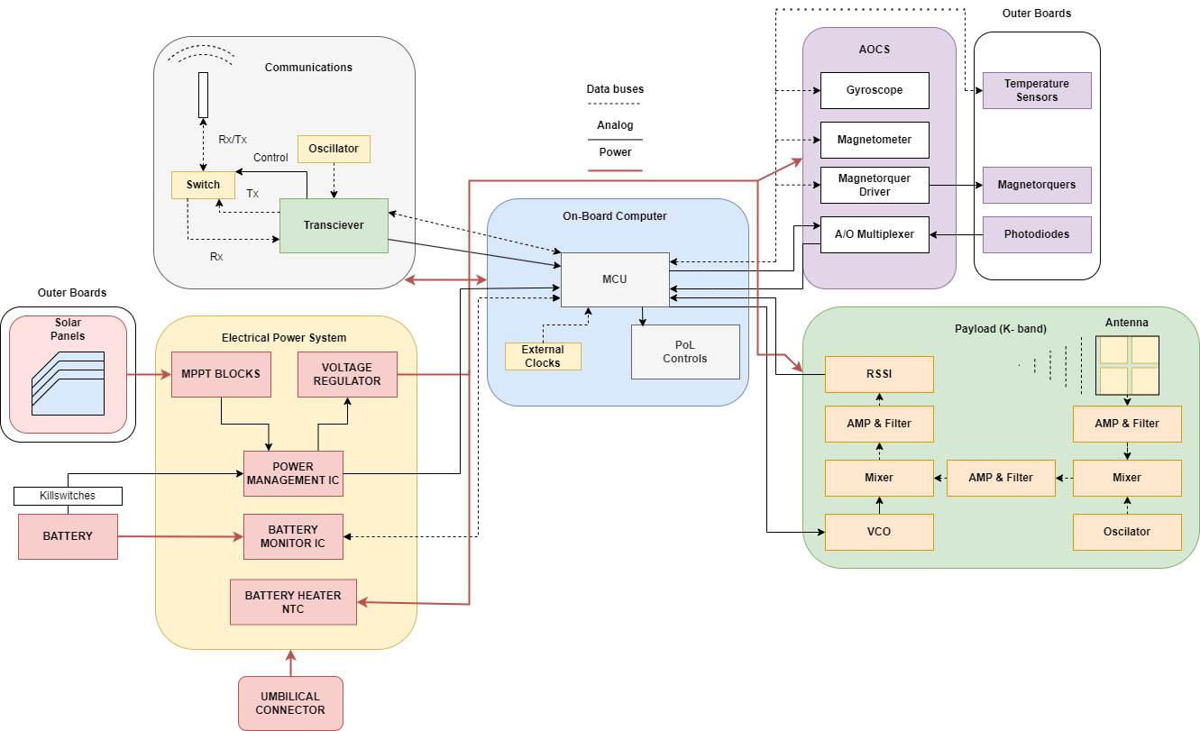
While it may appear complicated at first sight, this diagram should cause no fear once each subsystem (SS) is properly understood. To get some insight into the later a simple explanation of each SS component:
Communications (COMMS)
The COMMS subsystem main fuctions are to receive and send data through radio frequency (RF) waves. To do so it is provided of a monopole quarter-wavelenght antenna, with an approximate lenght of 8.6cm, designed to transmit at 868MHz. The signals to be sent by the spacecraft (telemetry) are generated and modulated by the transciever (combination of a radio transmitter and receiver). The signals received are also demodulated at the transciever.
The system is half-duplex as radio information (transmission and reception) can not be Tx'd and Rx'd at the same time. This is due to both the transicever capabilities and the use of a switch. The later regulates wether information is to be received or transmitted, and is controlled by the transciver itself which is, at the same time, controlled bu the MCU. In fact, all transciver control is done by the MCU through a Serial Peripheral Interface (SPI).
Note that the transciever requieres of an oscillator that provides a stable reference frequency.
Electrical Power System (EPS) & Power Generation
The EPS subsystem manages power distribution and regulation. Energy is obtained into the system through solar panels located at the lateral boards of the PocketQube. This energy is regulated by the MPPT blocks, one for each panel, and subministrated to the battery. Note that the killswitches ensure the satelite can't turn on when in it's rail before being deployed.
Power is distributed to the rest of the system after passing through the voltage regulator. Note that a battery heater is located in this board. The heater ensures that the battery temperature is constrained to higher than it's lowest operating temperature.
Finally, power can also be provided through the umbilical connector, still passing through the killswitches. The umbilical connector also provides code flashing into the MCU.
On-Board Computer (OBC)
The OBC subsystem's main component is the microcontroller unit (MCU). The MCU is in control of all data handling and on-board processing, acting as the brain of the spacecraft. Almost all information goes to or comes from the MCU and it is all stored there, either in its flash memory or in its random access memory (RAM).
Physically, on the OBC board will also be located the COMMS subsystem as well as point of load (PoL) controls and external clocks to ensure the proper timing of the MCU.
Attitude Determination and Control (ADCS)
The ADCS subsystem is the responsible for, as the name indicates, attitude determination and control. To do so it is equipped with a gyroscope, to measure it's angular velocity, a magnetometer to measure the local magnetic field, the magnetorquer driver, which controls the intensity that circulates through the magnetorquers, square, plain coils located at the lateral boards that provide torque via electromagnetic interactions, as well as an A/O Multiplexer that provides information on sun position.
Temperature sensors are also placed on the lateral boards in order to provide insight for future missions, as a tumbling mode to avoid heat is not possible with the current architecture.
Payload/K-Band (P/L)
The payload on ᴾᵒCat 3 measures RFI interference on the K-Band. To do so it is equiped with a patch antenna, several amplifiers and filters as well as mixers, one regulated by an oscilator and the other by a voltage controlled oscilator (VCO).
As mentioned several times, the architecture of this specific subsystem is completely dependant on the P/L. Note: RSSI means received signal strenght indicator.
Functional Architecture
The functional architecture of the spacecraft is defined by the different tasks or functions that each subsystem is designed to do. To this extent, all the operations done by the S/C can be categorized into the block diagram provided up next:
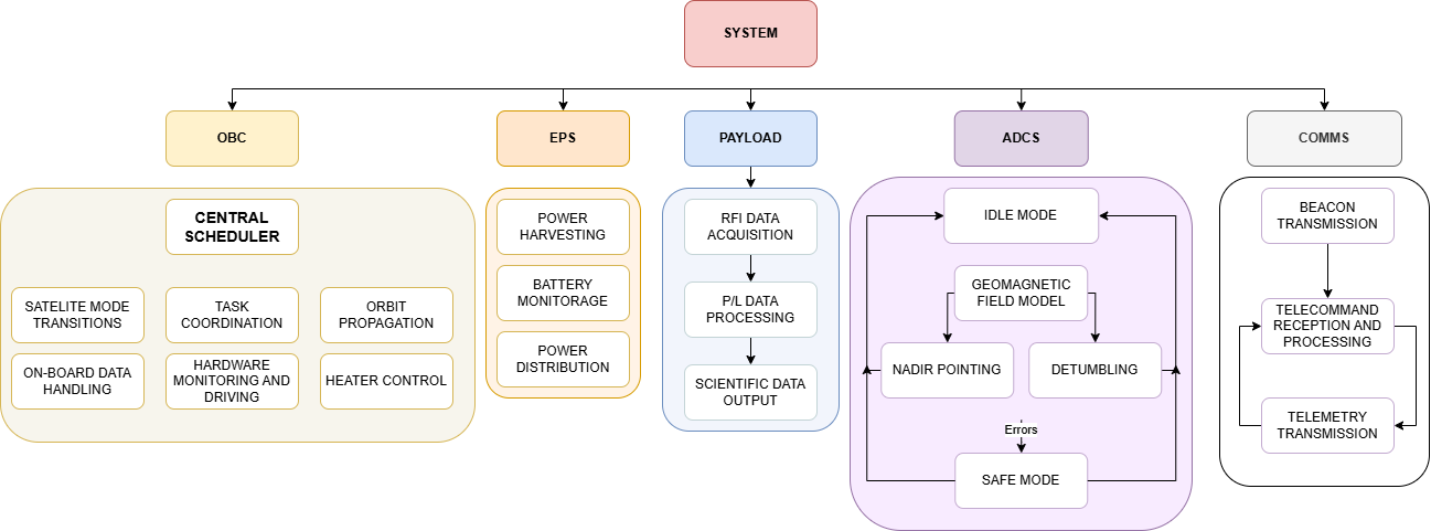
As it was done on the physical architecture explanation let's take a dive into the different parts in order to get a general overview. More information of each SS functionalities is found on their corresponding sections of the Wiki.
On-Board Computer (OBC)
The OBC is responsible for scheduling the different functions of the satelite. This is done through the coordination and control of software defined tasks programmed by the team. The OBC task itself is responsible of satelite mode transitions but the overall denominator of On-Board Software includes orbit propagation, housekeeping data management and On-Board data handling, heater control among other functionalities.
Electrical Power System (EPS)
The EPS is the subsystem responsible of power harvesting and maganagement, while also keeping track of the overall state of the required hardware and conditions to do so, mainly the battery. It will harvest energy through three solar arrays and distribute it to the rest of the system after conditioning the signal. During this process, should energy acquired be greater than the demands imposed by the system, it will charge the LiPo battery. Should the opposite happen, the subsystem is also responsible of discharging the battery and providing energy to the system.
Payload (P/L)
The Payload functionalities will differ greatly on the payload itself. In the ᴾᵒCat 2/3 case the payload will acquire and process RFI data that can be used for further scientific investigations. Other payloads design will find their functionalities confined to the tasks they are designed to perform.
Attitude Determination and Control System (ADCS)
The ADCS is responsible for two main functionalities. These are the nadir pointing (pointing the payload towards the Earth) and the detumbling (rotation stopping). During the process of performing these tasks other valuable byproducts are generated, such as magnetic field data and satelite orientation. The susbsytem will perform aformentioned tasks using a geomagnetic field model and the acquired sensor data.
Communications (COMMS)
The COMMS is responsible for telecommand reception, telemetry transmission and beacon transmission. Telecommands are instructions given the Ground Station (GS) to the satelite that indicate it to perform a certain task, be it taking a payload measure or calibrating the ADCS, among others. As telecommands are recieved it will be the system destined to process them and pass the corresponding instructions to the rest of the subsystems if required.
As mentioned before it will also periodically transmit beacons (depending on the state of the satelite) in order to send housekeeping data as well as a confirmation of overall correct state of the spacecraft.
Spacecraft System Configuration
In this page information into the spacecraft's measures is provided. Two diagrams are presented up next. The first one correspond to the measures of the PocketQube before the LoRa antenna deployment and the second one corresponds to the measures after deployment. The figures correspond to the ᴾᵒCat 3 (K-Band) S/C:

Figure 1.1: Stowed Configuration measures of ᴾᵒCat 3

Figure 1.2: Deployed Configuration measures of ᴾᵒCat 3
The next diagram provides an annotated exploded view render of the ᴾᵒCat 3 spacecraft:

Figure 1.3: Annotated Exploded ᴾᵒCat 3 View
Radiation Protection
Radiation
Radiation is a general denomination of all the high-energy particles and electromagnetic waves that exist in outer space, outside of Earth most inner layers of protective atmosphere and magnetic field. This radiation comes from multiple sources yet electronics are particularly vulnerable high-energy particles from Galactic Cosmic Rays (GCRs) and Solar Particle Events (SPEs). Radiation can cause malfunctions, known as single-event upsets (SEUs), which may lead to corrupted data, software crashes, or even permanent damage to sensitive components like microprocessors.
Considering this context measures have to be taken in order to avoid potential risks caused by the phenomena.
Measures taken
To limit the effects of radiation different measures are taken to ensure it’s effects are non-critical to the mission. Periodic reboots are performed after a configurable specified period of time in order to avoid potential persistent errors in the code created by radiation.
Power cycling is not performed as it is not compatible with our hardware design. Despite this, under certain battery charge conditions, the MCU power is shut down in order to prevent complete battery discharge. This may act in our favour in situations when the OBC doesn’t reduce it’s battery consumption due to it being stuck by radiation caused errors, performing a shut down power on cycle. EDAC and CRC measures are not currently designed or implemented, mostly due to most data handling being centralized ans straightforward.